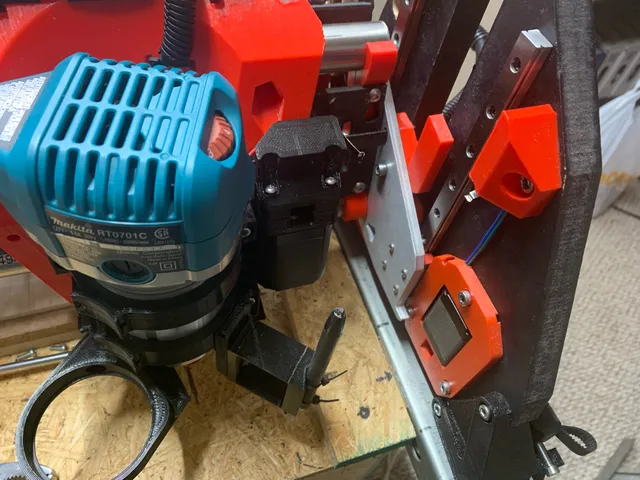
LowRider 3 CNC - reversal of homing on short axis (for swapping X & Y axes) (v1.3)
prusaprinters
See also.Want to swap X & Y axes on your LowRider v3? You'll probably need to flip which way the short axis homes. This works for that. It allows moving the X end stop switch (which would become the new Y end stop switch) from the left side of the LR Core to its right side. It also includes a replacement stub that includes a new bit that serves as the stop to trigger the switch. (Remember, the stopping point, for the switch to touch, has to be “part” of the whole assembly that raises and lowers with the beam itself. It's likely unworkable to try to use the YZ plate's flat side as the stop point, as you'd likely see the end stop switch get higher than the side plate itself while the beam is Z-homed to the top max, and then snap off your switch's trigger finger when then moving back downward.) You can get full details on both Marlin firmware edits and LowRider v3 hardware/wiring changes here: https://forum.v1engineering.com/t/swapping-x-and-y-axis-on-a-lowrider/25312/31?u=dougjosephYou can follow my LowRider upgrade from v2 to v3, here: https://forum.v1engineering.com/t/on-upgrade-path-lr2-lr3-clarksburg-wv-usa/32920/Printing:PLA is good. Print both parts as oriented. No supports needed. For both parts use 3-4 perimeter walls. For the remixed stub-right, use 70% infill. For the X end stop switch mount, use 30% infill. Installation:For clarity sake, any part descriptions based on axis names (X, Y) are given using original default axis names, with their intended new designations (for after the swap), sometimes shown in parentheses. Detach the X belt (soon to become the new Y belt).Detach the X end stop switch from the LR Core. This may be easier if you first detach one side of your beam from a side assembly, so you can temporarily remove your LR Core by sliding it off of the main beam.Attach the same X end stop switch (which is to become the new Y end stop switch) onto the printed part for it in this listing.Remove the front two short M3 screws holding your X stepper motor to the mount, which is still attached to your LR Core. There is no need to remove either the mount or the stepper from the LR Core. Two of four screws will hold the motor on while making the switch. Install the new end stop switch mount, by pressing its two downward “prongs” down into the screw wells on the top of the stepper motor mount, and by replacing the two short M3 screws with two M3 x 30mm screws. These screws will attach both the new end stop switch mount, and the stepper motor, to the motor mount.Loosen the two top set screws (aka grub screws) on the lead screw coupler on the right side assembly to release the lead screw. Remove the lead screw on the right side assembly.Remove the original stub-right from the right side XZ plate. Save the screw, and decide if you want to remove the embedded nut for re-use, or waste it to save time.Reinstall the X belt (soon to be Y belt) into the new stub right.Install the new stub-right onto the right side XZ plate. Don't forget to first insert an M5 nylock nut into the capture slot on the new stub-right. Reinstall the lead screw on the right side assembly.If needed, reinstall your LR Core. Re-run the wiring for the end stop switch, and reattach the X belt (now becoming new Y belt) to both the right side, LR Core, and left side.Adjust motor driver wiring and end stop wiring at your control board to suit the swapped X & Y axes. Details here.Re-flash your firmware to suit the swapped X & Y axes. Details here.Firmware Download:If you were using the V1 Engineering LowRider Dual Endstop firmware.bin file, and you are OK with a precompiled copy of it that has the changes for swapping X & Y, as detailed here., you can use the firmware.bin file provided (link below). If not, you may tweak the included editable source Marlin folder provided in the Zip file. It was made based on “Marlin_V1CNC_SkrPro_DualLR_2209_2.0.9.2_513-src.zip” which was downloaded from V1 Engineering, and is renamed as “V1CNC_SkrPro_DualLR_2209-2.0.9.2 (SWAP X & Y) 2022-06-21.zip.”Download link: http://design8studio.com/files/V1CNC_SkrPro_DualLR_2209-2.0.9.2-SWAP-X-Y-2022-06-21.zipControl Box:Need a control box? Or want to reorient your TFT to suit the new orientation of the swapped X & Y axes? If you are using BTT SKR Pro 1.2 board and BTT TFT35-e3 v3, then I offer this control box remix option based on Ryan's blank CAD file. If you are using a different board or TFT, then perhaps you can remix to suit it.Feel free to leave questions in the comments and I will do my best to respond. My PayPal tip jar: https://paypal.me/design8studio Various LowRider 3 CNC remixes:LowRider 3 CNC Collection View all my models and remixes on Printables:Design8Studio 3D models *Amazon product links are affiliate links.
With this file you will be able to print LowRider 3 CNC - reversal of homing on short axis (for swapping X & Y axes) (v1.3) with your 3D printer. Click on the button and save the file on your computer to work, edit or customize your design. You can also find more 3D designs for printers on LowRider 3 CNC - reversal of homing on short axis (for swapping X & Y axes) (v1.3).
