Light-Up LED Wand for Wizards and Witches - Clicky, Simple Print and Assembly
prusaprinters
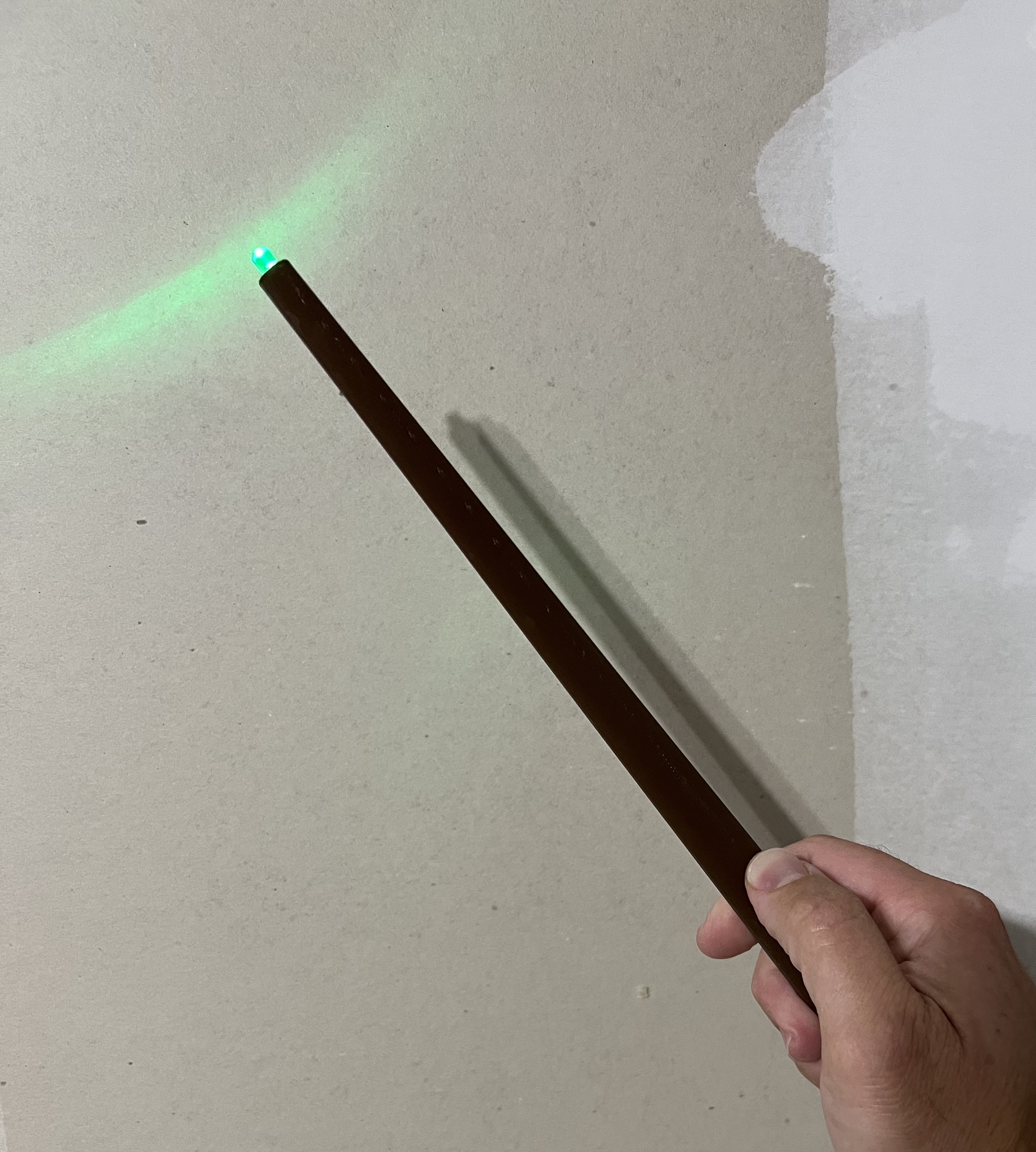
<h3>Introduction</h3><p>The kids wanted light-up wands to go with their witch/wizard costumes. We thought it would be fun to have the wands light up on demand, like when casting a spell. They made nice flashlights when trick-or-treating, too.</p><p>These wands are ultimately disposable. The components, including the batteries, are installed between the two halves, which then get glued together. I experimented with some ways to make the batteries replaceable, but settled on this for aesthetic reasons and production speed. Since the LED is only illuminated when the button is pressed, hopefully they’ll last a good long while. Optimistically, there’s 10 hours of run time (~120mAh LR44 capacity / 20mA for the LED). They’re still fun even if they can’t light up, too.</p><h3>Design Thinking</h3><p>We really wanted a slim, tapered cylinder, rather than some of the other designs out there that have wider, straight cylinders at the base and a separate tapered end. This ruled out a traditional battery holder. Instead, I decided to use a stripped length of solid wire to make contact with the batteries. I experimented with putting a CR2xxx coin cell on edge at the base and sliding the wires down the sides, but it made the design pretty wide. I explored a CR123 battery, but routing a wire down to one end of the battery seemed like a pain, and I didn’t want to add a spring to tension the battery against it. Ultimately, I went with two 1.5v LR44 batteries, in series, pressed against wires that are just slightly recessed next to the positive and negative contacts. By seating them in opposite sides of the wand, the system gets tensioned when the two halves are glued together.</p><p>In the spirit of keeping it simple, I decided to just directly click a tactile switch to operate the light, rather than design and print a tiny, curved piece to act as a button that would hit the switch. The consequence of this is that a tall switch is required to get the actuator up and out of the hole. After some experimentation, I added a platform to support the switch from underneath, resulting in good stability when clicking. I bulged in the walls on the sides of the switch to help keep it in place during assembly and when in use. The fit is tight and the switch gives a good “snap” when pressed down onto the platform.</p><p>Also notable, is that there’s ample channel in which to recess the wires. I made the inside lips somewhat thick, however, to facilitate easy printing and to give good surface area to glue.</p><h3>Printing</h3><p>Print each half with the flat-side-down on the bed with support.</p><p>Support especially helps with the battery chamber. The tolerances there are tight. Without support, the drooping plastic messed up the wire channel and didn’t let the battery sit flat, without cleanup work.</p><p>Note: This orientation results in visible layer steps when the dome is printed at .2mm. It’s good enough, makes for a quicker print, and looks a little bit like a wood grain, thanks to the taper toward the tip. I actually got positive feedback from non-printing people about this.</p><h3>Recommended Pieces for Assembly</h3><p>1 - 5mm LED of your choice - <i>don't forget a resistor, if needed</i></p><p>1 - 6x6mm tactile switch with a 10mm actuator or longer</p><p>2 - 1.5v LR44 batteries</p><p>~100mm - 22ga solid wire - <i>necessary for contact with the batteries</i></p><p>~400mm - 22ga stranded wire - m<i>uch easier to work with and allowed for nice bends at the switch legs.</i></p><p>Superglue (CA glue) - <i>wear gloves!</i></p><h3>Assembly</h3><p>See pictures for an example assembly. Wire lengths listed are approximate. I found it helpful to start with a little too much and trim one or more wires during assembly to make sure everything was JUST long enough. </p><p>My process was roughly:</p><ol><li>Solder a sufficient length of stranded wire (~185mm) to one side of the tactile switch.</li><li>Solder a much shorter length of stranded wire (~35mm) to the other side of the tactile switch.</li><li>Snap the switch into place.</li><li>Check in on where we are lengthwise and trim the wire from Step 1 if needed.</li><li>Take the switch back out.</li><li>Slide a piece of heatshrink onto the wire from Step 1.</li><li>Solder the unused end of the wire from Step 1 onto the positive leg of the LED.</li><li>Solder a sufficient length of stranded wire (~230mm) to the negative leg of the LED.</li><li>Slide a piece of heatshrink onto the wire from Step 8.</li><li>Position the two pieces of heatshrink on the LED leg joints and shrink.</li><li>Cut two lengths of solid wire (~50mm or less).</li><li>Strip ~12mm from one end of each of the solid wires. These ends will contact the batteries.</li><li>Check in on where we are lengthwise with everything.</li><li>Join the stranded and solid wire pairs (I used solder).</li><li>Insert the exposed ends of the solid wires into the battery chambers.</li><li>Insert the batteries with the negative and positive sides facing the correct directions. I found the small “pushpin” magnet pictured to be helpful getting the batteries in and out.</li><li>Snap the switch into place if it’s not already.</li><li>Line everything up so that the switch actuator is poking through the hole and wires are stowed in the channels while bringing the assembly together.</li><li>Test.</li><li>Separate the assembly a little bit and apply glue around the inside perimeter lips.</li></ol><h3>Room for Improvement</h3><p>If I ever come back to it, I would considering coming up with a way to ensure the halves line up perfectly when glued together. Right now it’s down to slapping glue on there and holding it together evenly (not that hard, though!). Because of the printing orientation, I couldn’t add tabs or pins to line up the pieces, but perhaps I could add holes and bring in other pieces (toothpicks?) to act as alignment pins.</p><p>I would also explore adding a bit of a rim on which to seat the bottom of the LED and keep it protruding out of the tip about half way. I’ve made five of these and a couple ended up more than halfway out and a couple less than halfway out. This was down to how much wire I used. I wasn’t that concerned about being consistent, though, and just pressed on.</p><p> </p><p><strong>If you make one, please share! Enjoy!</strong></p>
With this file you will be able to print Light-Up LED Wand for Wizards and Witches - Clicky, Simple Print and Assembly with your 3D printer. Click on the button and save the file on your computer to work, edit or customize your design. You can also find more 3D designs for printers on Light-Up LED Wand for Wizards and Witches - Clicky, Simple Print and Assembly.