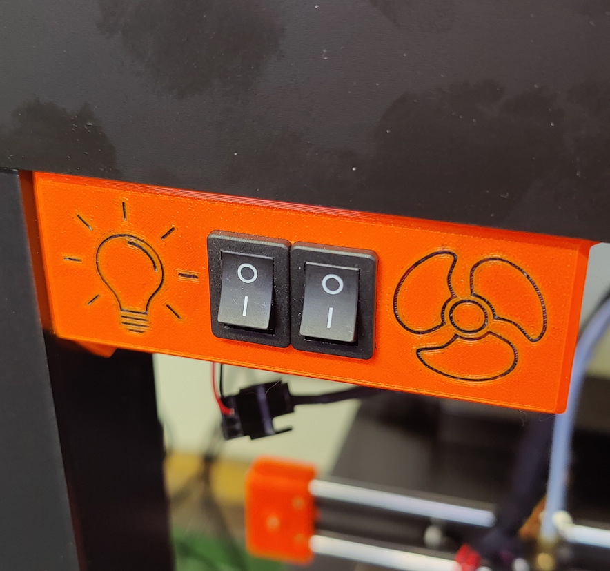
Light & fan switch box for Ikea Lack enlosure
prusaprinters
<p>A small box to allow for power distribution to a fan and lights, with switches to turn them on and off. The front panel has symbols indicating what the switches operate, and the rear panel has labels indicating what connectors should go there (12V DC input, Fan, and Lights). For your own use you may use any DC voltage input you feel is suitable; the lettering was for my convenience as I was using a 12V Noctua extractor fan and 12V LED strip lighting, with a 24V to 12V step-down DC-to-DC converter to draw from the 24V MK3S+ power supply.</p><p>Uses additional components:</p><ul><li>1x Veroboard/Stripboard 25 X 64mm</li><li>3x 2.54mm Dupont Connector XHPX-2J connectors (male & female)</li><li>1x 2.54mm Dupont Connector XHPX-2J connector (male & female)</li><li>2x 15mm Mini Rocker Toggle Switches</li><li>4x M3x10 socket screws (thread holes can accommodate longer, up to about M3x20)</li><li>2x wood screws to secure to Ikea Lack frame</li><li>Suitable insulated wire for internal and external wiring</li></ul><p>Loosely place three female XHPX-2J connectors into the veroboard, noting in the photographs both position (allowing connectors to exit through the hole in the rear panel) and rotation (this will place positive and negative terminals at the same location on the male connectors, for ease of external wiring. Negative terminals were indicated on my photos by a black pen mark). Place the veroboard into the slot in the rear of the front panel resting on the four corner stands, and test the fit with the holes in the rear panel. You may need to rotate the board 180 degrees to get the holes to line up properly, as the veroboard may not be completely symmetrical. Once happy with the fit and the orientation of the connectors, solder the connectors into place.</p><p>Solder a female XHPX-2J connector into the veroboard in the position shown in the photograph. The pair of wires labelled “LX” feed the light switch, and the pair of wires labelled “FAN” go to the fan switch.</p><p>Solder two short lengths of insulated wire to link two pairs of copper tracks together, as shown in the photographs.</p><p>Solder two pairs of insulated wire of length approximately 8cm onto the contacts at the rear of the switches. Crimp male connectors to the other ends, and insert into a male XHPX-4J connector; orientation does not matter as long as one switch's pair of wires occupies the left two connectors, and another switch's pair of wires occupies the right pair. Insert the connector and wires through front of the hole in the front panel. Line the switches up side-by-side in front of the hole, ensuring the fan switch is next to the fan symbol and the light switch is next to the light symbol (you can tell which is which by looking at the orientation of the XHPX-4J connector on the photograph). Push the switches into the hole where they should lock in place.</p><p>Lay the wiring up into the smaller notch in the cavity behind the front panel, and locate the veroboard into the notches so the wiring pokes out. Fold the wiring over and push the XHPX-4J male connector into place. Push the remaining wiring back into the cavity. Place the back cover over the veroboard locating the connectors into the hole, and secure in place with the four M3x10 screws.</p><p>Secure the box under the Ikea Lack table against the left leg using screws through the two attachment holes. Wire the DC input, fan wiring, and light wiring to three male XHPX-2J connectors; polarity of wiring can be either way as long as it is consistent across all three connectors, but I would suggest following the polarity indicated in the photographs for ease of replication.</p><p>For better visualisation the recessed symbols can be highlighted, for example by being inked or painted as in my example in the photos, or by performing a filament change at the layers behind the recess.</p>
With this file you will be able to print Light & fan switch box for Ikea Lack enlosure with your 3D printer. Click on the button and save the file on your computer to work, edit or customize your design. You can also find more 3D designs for printers on Light & fan switch box for Ikea Lack enlosure.
