LED Ring Lamp (esp, wifi)
prusaprinters
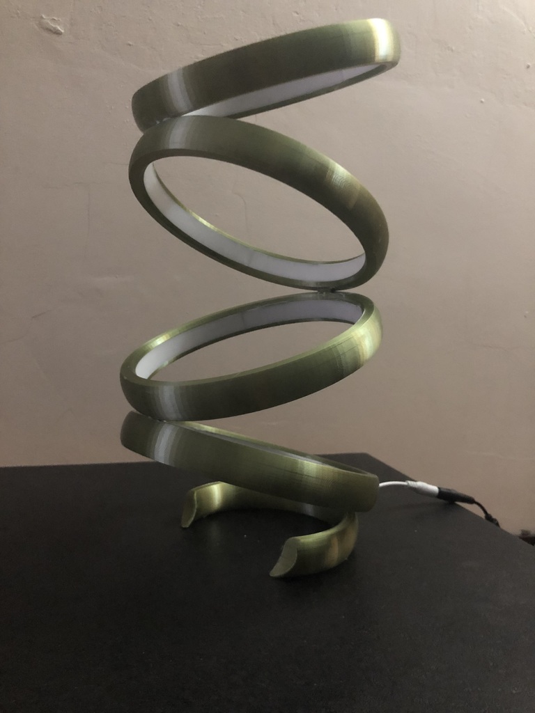
<p>Inspired by <a href="https://www.thingiverse.com/thing:2171804">https://www.thingiverse.com/thing:2171804</a></p> <p>An interesting lamp which makes good use of the shiny filament I had. I wanted something fun to print with this stuff.</p> <p>The lamp hides a wifi led controller in the base, and the base is then supplied with a little added weight by stuffing it full of spare washers and then hot glue to keep them still!</p> <p>The rings are fitted with LED strips, and wired through a channel in each ring. The wiring is the worst part of the build, but once done it is worth it!</p> <h3>Print Settings</h3> <p><strong>Printer Brand:</strong></p> <p>Prusa</p> <p><strong>Rafts:</strong></p> <p>No</p> <p><strong>Supports:</strong></p> <p>No</p> <p><strong>Resolution:</strong></p> <p>0.15</p> <p><strong>Infill:</strong></p> <p>30% line for rings, 100% for connector and diffuser</p> <p><strong>Filament:</strong> PLA</p> <p><strong>Notes:</strong></p> <p>Filament: Uniqstore PLA Silk Bronze</p> <p>Printer Prusa i3 Mk2S</p> <p>Why does thingiverse add links to amazon if I enter those details in the right place?</p> <h3>Post-Printing</h3> <p><strong>Assembly instructions</strong></p> <p>Print three main rings and one top ring (top ring is the same, just without the top socket)</p> <p>Print three diffuser pieces per ring, so a total of 12.</p> <p>Print three main connectors.</p> <p>Print the base and base connector.</p> <h3>Start build.</h3> <p>Start by inserting the LED strips into each ring. Cut an appropriate length, remove the adhesive backing and fit into the ring. There is a very small channel at the bottom of the ring where the strip should latch into by 1mm. The glue on these things is awful so clipping the strip into this really helps it stay in place. Some superglue can be added if you need it, but avoid adding it at this stage incase something needs to be corrected.</p> <p>The start/end points of the LED strips differs depending on the ring. The top ring should start by the bottom socket. The middle two rings start near the top socket and the bottom ring should start near the bottom socket. Reason for this will become clear when wiring starts.</p> <p>Add the connectors. The connector is not symmetrical, the longer part goes into the top of the ring. As the top ring does not have this, fit a connector into the bottom of the top three rings. The bottom ring has a different connector.</p> <h4>Checkpoint reached. You now have four rings, with LED's inserted, and three of them have the connector in the bottom of them.</h4> <h3>Next step.</h3> <p>Wiring. I used silicon wire but anything will do. The base connector will have five wires running through it, the other connectors at most will have four, so make sure your wire will fit.</p> <p>I used just a red and a black wire, but it would be better to use red for +Ve and four other colours for each ring ground.</p> <p><em>top ring</em></p> <p>Pass two wires through the bottom connector of the top ring. Solder them carefully to the terminal points of the LED strip in the top ring. Use flux if you have it. Be careful not to melt the plastic! Once connected, I'd recommend connecting it to 12V and checking that the strip is working well.</p> <p><em>next ring</em></p> <p>Pass those two wires down through the top socket of one of the two middle rings (with the strip terminating by the top socket)</p> <p>Connect the two rings together, it should be a very snug friction fit. Glue isn't needed but can be used.</p> <p>Cut the positive wire by the terminal on the LED. The ground wire needs to travel through the ring to the other side so it can be passed down the bottom socket. A new positive wire should pass through the other half of the circle.</p> <p>Solder both positive wires to the positve terminal on the LED strip, connect its ground wire. Pass the positive and the two ground wires through the connector at the bottom of ring 2.</p> <p><em>next ring</em></p> <p>Connect the assembled two rings to the next middle ring, passing the three wires in.</p> <p>Cut the positive wire again, pass the two existing ground wires through the ring, and add a third one. Send a positive wire through the other way.</p> <p>Connect up the two positive wires, the new ground wire and pass the four wires down through the connector.</p> <p><em>bottom ring</em></p> <p>Bring the four wires in and connect the rings.</p> <p>Pass the ground wires through the ring one way and the positive the other way (this isn't essential, you can mix them if you want). Exit the wires at the other side of the ring and cut the positive in the obvious position. Pass the three grounds down through the connector. From there, those grounds only need a few inches of spare length.</p> <p>Bring a new ground and positive wire into the bottom connector and make the appropriate solder connections.</p> <p><em>done?</em></p> <p>At the bottom of the bottom ring should now be one positive line and four ground lines. Test each ring of you feel sensible.</p> <h3>diffusers</h3> <p>At this stage, the lamp part is built, and if it has ben tested and works, the diffusers could be glued in place now. Three per ring. They're sided and there's a lip at the bottom of each ring for it to sit against. Use superglue and be careful not to use too much. (I used too much, as can clearly be seen in the photos)</p> <h3>Connect to base</h3> <p>The lamp assembly is done, bring the wires through the base connector and connect the base to the rings.</p> <p>From here, the wiring will vary depending on your LED controller, and honestly, if you got this far I think you can work this part out for yourself.</p> <h3>Base assembly</h3> <p>Fitting the LED controller into the small pocket, and getting the wiring into it is definitely possible, but I didn't design it to be easy! You're on your own for this part!</p> <h3>Base weighting</h3> <p>To add stability, the base of the lamp needs to be heavy, and PLA isn't. The two 'arms' of the base have voids at the bottom, fill these with sand, or lead shot or anything heavy you can find.</p> <h3>How I Designed This</h3> <p><strong>Inspired by...</strong></p> <p>Once I saw <a href="https://www.thingiverse.com/thing:2171804">https://www.thingiverse.com/thing:2171804</a> I knew I must have one, but I struggled to print it. After 5 failed attempts, I decided to just build my own.</p> <p>This design is absolutely inspired by that make, but is created completely from scratch in OnShape design.</p> <p>I wanted the design to be easy to print, to need no supports, and to have (mostly) hidden wires. There are channels around the rings for the wiring to run.</p> <p>I also wanted it to be controllable from a phone or automation system. I linked the four rings to a cheap RGB(W) controller. Each ring has only white LED's but each is connected to a different channel on the controller, so asking for "red" will turn on only one ring. Combined with the brightness control, this makes the lamp very variable in how it should light up.</p> Category: Decor
With this file you will be able to print LED Ring Lamp (esp, wifi) with your 3D printer. Click on the button and save the file on your computer to work, edit or customize your design. You can also find more 3D designs for printers on LED Ring Lamp (esp, wifi).