LED Light Ring
myminifactory
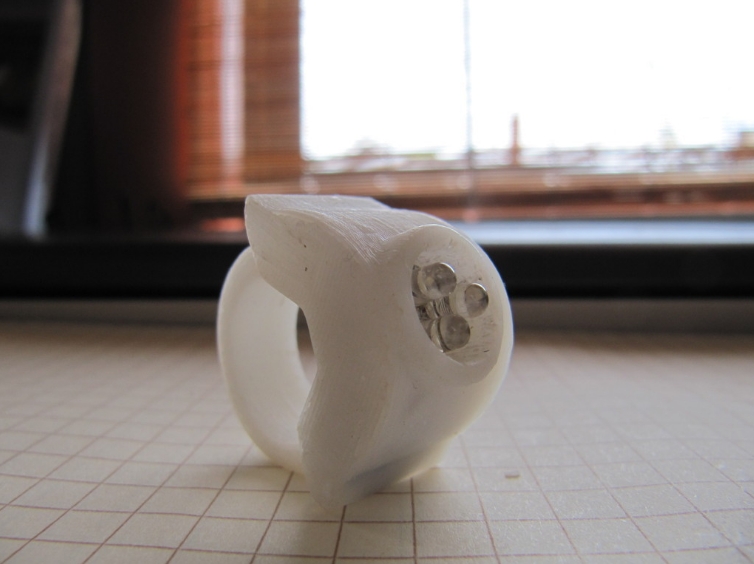
Motivation: I constantly require a small amount of light at my fingertips, and my cell phone just isn't enough. My goal is to design a compact yet powerful flashlight ring. Details: So far, I've tried two switch mechanisms. The first one had the head slide laterally, perpendicular to my finger, but it wasn't very comfortable. This current model slides forward and backward instead. However, this too has its drawbacks - it requires both hands to turn on and off, and the top is prone to falling off. I think the next version will try to have a twisting activation mechanism. Software: The model was designed using openscadpy (my first project, so sorry for the poor code quality): github.com/hmeyer/openscadpy Hardware: The model was printed on an up! 3D printer (pp3dp.com) My intent is for this product to be Open Hardware, under the TAPR OHL: tapr.org/TAPR_Open_Hardware_License_v1.0.txt Instructions Tools: * Up! 3D printer or equivalent * Support removal hand tools * Wire cutters * Soldering equipment Bill of Materials: (1) Ring base, printed (1) Ring head, printed (2) Coin cell battery, http://www.sparkfun.com/products/337 (1) 1 SPDT slide switch, http://www.sparkfun.com/products/9609 (1) Triangular proto board, http://www.sparkfun.com/products/8887 (3) Bright LEDs (3+) Extra lengths of wire Assembly Instructions: Print both parts. The size of the ring can be adjusted in the openscadpy file, but you may need to print multiple sizes to find a good fit. Be careful not to get stuck with too many rings. Wire up the triangular proto board. This part is a bit tricky, and my method isn't ideal. The slide switch is in the center on one side of the protoboard, and the LEDs are on the opposite side. Once through the board, group and solder the positive and negative leads together. Attach the positive group to one side of the slide switch. The other side of the switch will connect to the positive battery lead, and the negative group of the LEDs will go to the negative battery lead. Test the circuit once complete, then push the protoboard unit into the ring head. Install coin batteries. A good way to do this is to run wires through the gap so that an inserted coin cell connects and holds it in place. Run two such wires on the LED side of the gaps; one goes to the slide switch, and the other goes to the LEDs. Add another wire connecting the two batteries. Insert the batteries: the positive end of one runs into the slide switch, and the negative end of the other runs into the LEDs. Be careful not to create short circuits - unfortunately, I haven't found an easier way to do this. Orient the completed unit so that the slide switch can snap into the ring base. This work is licensed under a Creative Commons Attribution 4.0 International License. LED Light Ring by CarryTheWhat is licensed under the Creative Commons - Attribution license.
With this file you will be able to print LED Light Ring with your 3D printer. Click on the button and save the file on your computer to work, edit or customize your design. You can also find more 3D designs for printers on LED Light Ring.