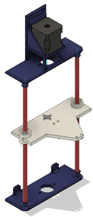
Lead Screw Driven Linear Motion System with NEMA 17 Stepper
thingiverse
These files enable linear motion using 8mm rods, a lead screw set, and a NEMA 17 stepper motor. Originally designed for vertical motion in Senior Design 1 Fall 2019 at Clemson University for a Towers of Hanoi project. Additional Hardware Needed - NEMA 17 Stepper Motor [Amazon](https://www.amazon.com/STEPPERONLINE-Stepper-Bipolar-Connector-compatible/dp/B00PNEQKC0/ref=sr_1_5) - Linear Bearings - I used solid polymer bearings. [Amazon](https://www.amazon.com/Printer-Solid-Polymer-LM8UU-Bearing/dp/B06XPRCMJS/ref=sr_1_10) - Lead Screw T8 + Copper Nut + Coupler+ Pillow Block Bearing Set [Amazon](https://www.amazon.com/gp/product/B07567KZB3/) - 4 M3 bolts, 1 M4 bolt (~25mm), 1 M4 nut - 8mm linear rod pair of desired length (Must be shorter than the lead screw) Assembly Instructions As shown in the image, you print one of each file. Connect the NEMA 17 stepper motor to the top piece using 3mm bolts, then attach the coupler to the stepper shaft. Next, attach the two pillow block bearings to the 3D printed parts using M3 bolts and nuts. Don't tighten them yet, they might need to move a little bit once we install the lead screw. Install the lead screw in the coupler. Next, spin the flange halfway up the lead screw. Once it's about halfway up then attach the flange to your 3D printed sliding piece using M3 bolts. Now you can put in the 8mm smooth rods on the sides, sliding them through the polymer bearings in the 3D printed parts and then into the holders of the top and bottom pieces. Finally, install the 3D printed end piece to hold everything together. At this point you can go through and tighten all the bolts on the pillow blocks, but make sure you can still easily spin the lead screw by hand. If things are off by 1mm the wrong direction you won't be able to spin the lead screw. Notes and Tips I designed this to work with approximately 11" long linear rods, but it should work with any length. If you run into noise issues with the stepper motor try loosening all the bolts and nuts holding things in place, or maybe try moving the stepper motor around. Basically it's vibration due to parts not being perfectly aligned. The top and bottom parts should print without supports just fine. My sliding plate has some small offsets for our gripper, but if you don't need them then just delete them. Bonus Files Gripper: Our project involved gripping rings of variable size from 2" up to 5.5", so we found/printed a parametric gripper. The "Gripper V4.zip" file is my SCAD file modified to fit up to 5.5" objects, while being driven by a standard cheap servo motor. [Original Thingiverse link](https://www.thingiverse.com/thing:27468)
With this file you will be able to print Lead Screw Driven Linear Motion System with NEMA 17 Stepper with your 3D printer. Click on the button and save the file on your computer to work, edit or customize your design. You can also find more 3D designs for printers on Lead Screw Driven Linear Motion System with NEMA 17 Stepper.
