LDR Array for Solar Tracker
thingiverse
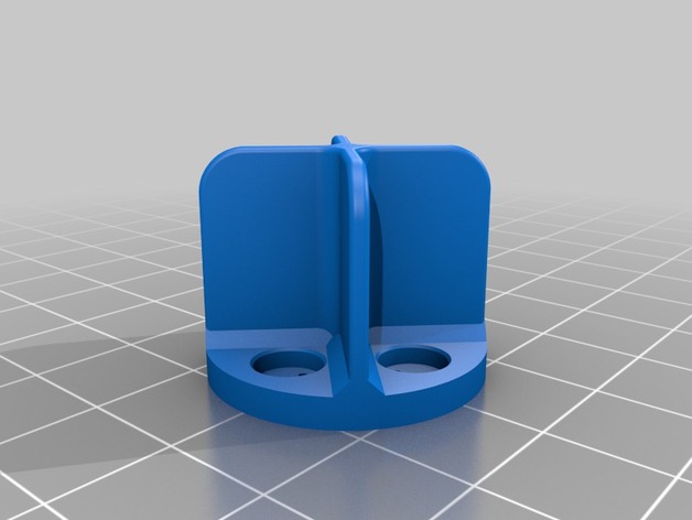
This is a simple setup for a solar tracker I am creating. As such, it only includes a dummy light-dependent resistor I uploaded to Thingiverse yesterday, located at http://www.thingiverse.com/thing:858043. Analogue pin A0 connects pairs 1 & 2 together, and analogue pin A1 connects pairs 3 & 4. Meanwhile, test pin 9 can be raised to HIGH for testing purposes - which may or may not save power! (That remains to be seen.) Here's how I have the components connected: * Ground - Light-dependent resistor 1 - A0 - Light-dependent resistor 2 - positive (+ve) on Pin 9 * Ground - Light-dependent resistor 3 - A1 - Light-dependent resistor 4 - +ve on Pin 9 There are two pairs of light-dependent resistors, each consisting of a single pair with one side connected to ground and the other to a common voltage. Both of these pairs connect their other sides together at analogue pins A0 and A1 respectively. The light-dependent resistor layout I used was: * Set 1: Light-dependent resistor 1 is directly next to set number four * Set three, in turn, lies right beside light-dependent resistor 2 Set 1 consists of two components connected together; specifically sets three and four. When both are set 4 the entire connection will be grounded, as it were. Ground pins have a strong relationship with one another and thus when combined can result in numerous unique effects, so keep that in mind. Each is vital in understanding just how a solar tracker functions overall. Choice table options are divided up like this:
With this file you will be able to print LDR Array for Solar Tracker with your 3D printer. Click on the button and save the file on your computer to work, edit or customize your design. You can also find more 3D designs for printers on LDR Array for Solar Tracker.