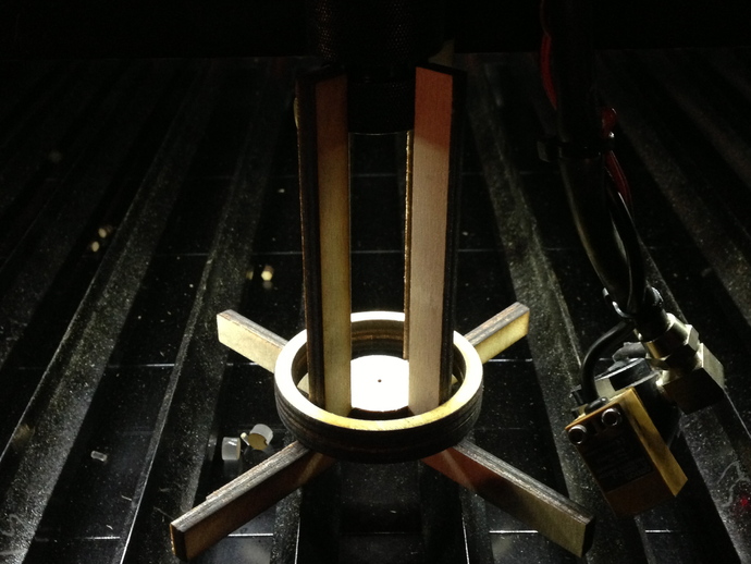
Laser Cutter Z-Axis Parametric Alignment Jig
thingiverse
Create an adjustable jig for perfectly aligning your laser cutter's Z-axis. Experimenting with pen and paper alignment methods proved challenging, but this tool drastically improved accuracy while simplifying the process. Crafted from Baltic birch or easily cuttable acrylic, it's ideal for lasers without precise Z-axis calibration. To begin, measure crucial parameters: nozzle width (Nozzle_Dia), laser nozzle height (height), table blade intervals (basewidth), and material thickness (MaterialThickness). Input these values into the OpenSCAD document for construction verification. Export as a 2D projection DXF file, correcting any errors within the file if needed. Make multiple target disks for alignment adjustments and send the DXF to your preferred laser cutter. Assemble the jig, gluing the structure but leaving platform disks unglued for replacement. Include two rings for stability, though one may suffice. Position the jig under the laser, ensuring a 3x material thickness Z-axis adjustment. Test and adjust mirrors until satisfied, replacing disks as needed. This process might require multiple attempts, but once aligned, it'll be worth it! A shorter fourth fork allows it to fit over the nozzle without Z-table readjustments, while proper focus should be on the disk placed on the platform.
With this file you will be able to print Laser Cutter Z-Axis Parametric Alignment Jig with your 3D printer. Click on the button and save the file on your computer to work, edit or customize your design. You can also find more 3D designs for printers on Laser Cutter Z-Axis Parametric Alignment Jig.
