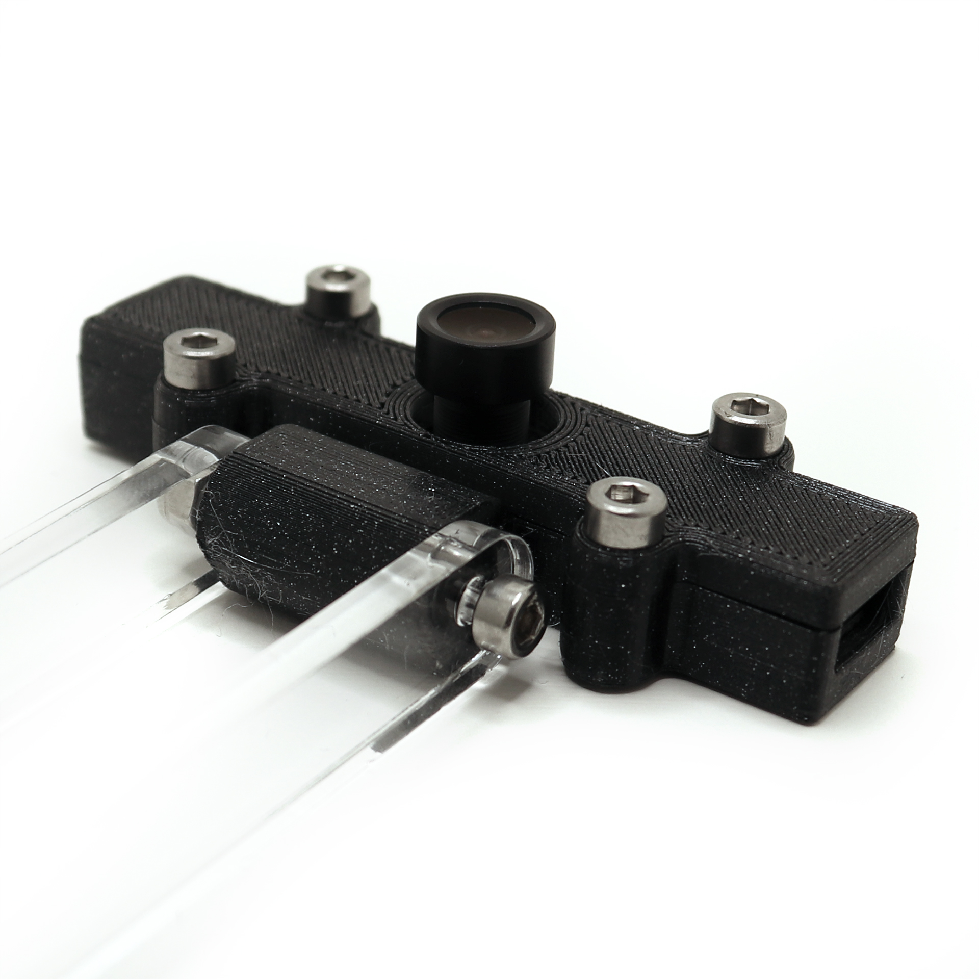
Laser cutter camera arm
prusaprinters
<p>I got an OMTech 50W CO2 laser that I needed a way of mounting a camera to. First I got the camera mounted to the lid as I have seen many people do. The lid was a bit to flimsy and the gas springs had an unreliable end point which meant the camera didn't end up in the same position. So I made a spring tensioned camera holder instead.</p><p> </p><h4>Printed parts needed to make this</h4><figure class="table"><table style="border:0px solid #F5F5F5;"><tbody><tr><td style="border:0px solid #F5F5F5;"><ol><li>Base</li><li>CameraBase</li><li>CameraLid</li><li>LeftHolder</li><li>MiddleHolder</li><li>RightHolder</li><li>SpacerX3 </li></ol></td><td style="border:0px solid #F5F5F5;"><figure class="image"><img src="https://media.printables.com/media/prints/283468/rich_content/6adf5667-bc59-4f35-84d8-2a9e0d2e7a7c/sheet1-1.jpg#%7B%22uuid%22%3A%2250d35de5-cae7-47f6-833a-e6cbaf9bccab%22%2C%22w%22%3A2175%2C%22h%22%3A1883%7D"></figure></td></tr></tbody></table></figure><p> </p><h4>Other parts needed</h4><ul><li>13 x Lock Nut DIN 985 M3</li><li>2 x Hex Nut DIN 934 M3</li><li>8 x Swuare Nut Din 562 M3</li><li>4 x Screw DIN 912 8 mm M3</li><li>8 x Screw DIN 912 12 mm M3</li><li>4 x Screw DIN 912 16 mm M3</li><li>2 x Screw DIN 912 22 mm M3</li><li>4 x Screw DIN 912 30 mm M3</li><li>3 x Screw DIN 912 45 mm M3</li><li>2 x Laser Cut Acrylic Arms</li><li>1 x Lightburn Official Camera</li><li>4 x Springs 6 x 20 mm</li></ul><p> </p><h4>Assembly instructions</h4><figure class="table"><table><tbody><tr><td><figure class="image"><img src="https://media.printables.com/media/prints/283468/rich_content/191111ce-ac79-491e-846f-2f183fc6cf21/img_5605.jpg#%7B%22uuid%22%3A%22271cf7f8-eb9b-49f2-9c12-f929ba01c91c%22%2C%22w%22%3A1920%2C%22h%22%3A1920%7D"></figure></td><td><figure class="image"><img src="https://media.printables.com/media/prints/283468/rich_content/01ce9643-0399-44c6-8bdc-50660149c61d/img_5606.jpg#%7B%22uuid%22%3A%227624fd02-2b9a-45b5-a008-757ddd827f3a%22%2C%22w%22%3A1920%2C%22h%22%3A1920%7D"></figure></td><td>Start by inserting all the square nuts. Make sure there are no obstacles and that they are pushed all the way down. Use a small allen key or a flat head screwdriver. </td></tr><tr><td><figure class="image"><img src="https://media.printables.com/media/prints/283468/rich_content/bd881d46-caee-4623-ac0b-562af62ac0a0/img_5607.jpg#%7B%22uuid%22%3A%220f211a7b-f6ad-4444-8b37-679b24bdbacf%22%2C%22w%22%3A1920%2C%22h%22%3A1920%7D"></figure></td><td><figure class="image"><img src="https://media.printables.com/media/prints/283468/rich_content/d4bbea7f-9b5a-4097-ba2e-e814badd7bbc/img_5608.jpg#%7B%22uuid%22%3A%22fa699f70-6965-4d31-b86f-4437bed8ded6%22%2C%22w%22%3A1920%2C%22h%22%3A1920%7D"></figure></td><td>Mount the middle and side holders to the base using eight 12 mm screws.</td></tr><tr><td><figure class="image"><img src="https://media.printables.com/media/prints/283468/rich_content/c1afa3b9-84d4-4428-8134-de7cf3985a5f/img_5609.jpg#%7B%22uuid%22%3A%2259e16e2b-0c53-4711-9e2e-9b615a11ee21%22%2C%22w%22%3A1920%2C%22h%22%3A1920%7D"></figure></td><td><figure class="image"><img src="https://media.printables.com/media/prints/283468/rich_content/931b2fc3-d7ab-4939-9081-22087d13d82a/img_5612.jpg#%7B%22uuid%22%3A%2275502598-bac7-48b1-a1c6-27d7afe144bc%22%2C%22w%22%3A1920%2C%22h%22%3A1920%7D"></figure></td><td>Insert the two 22 mm screws in the acrylic arms and fasten them with hex nuts. There are several holes to be able to adapt it to different springs. Note that the holes on the ends are for spacers and mounting the arms to the base. Insert the spacers and secure them with 30 mm screws and lock nuts.</td></tr><tr><td><figure class="image"><img src="https://media.printables.com/media/prints/283468/rich_content/3be93186-a1cb-4952-aa49-2dc2fce623a5/img_5614.jpg#%7B%22uuid%22%3A%22e253328f-40b2-420e-b43b-0dfd0c8f461e%22%2C%22w%22%3A1920%2C%22h%22%3A1920%7D"></figure></td><td><figure class="image"><img src="https://media.printables.com/media/prints/283468/rich_content/97a2afb3-5cfe-4012-ad20-b60107c957ec/img_5615.jpg#%7B%22uuid%22%3A%2288999bb0-6abd-4e1b-9fc4-3d846cc46968%22%2C%22w%22%3A1920%2C%22h%22%3A1920%7D"></figure></td><td>Use a 30 mm screw to mount the camera base to the arms. Fit the arms into the holder and secure them with a 45 mm screw and a lock nut. Insert another 45 mm screw in the hole just above and tighten with a lock nut. Make sure you don’t overtighten and that the arms can move freely.</td></tr><tr><td><figure class="image"><img src="https://media.printables.com/media/prints/283468/rich_content/44708d06-1e67-4b6c-a257-f52b9b4f79ef/img_5616.jpg#%7B%22uuid%22%3A%226ce3a825-b9b5-4698-98e4-3e9bd206ee73%22%2C%22w%22%3A1920%2C%22h%22%3A1920%7D"></figure></td><td><figure class="image"><img src="https://media.printables.com/media/prints/283468/rich_content/8b1fc8a5-7e0d-4e23-b45b-806a5221637d/img_5618.jpg#%7B%22uuid%22%3A%229c83c09b-12c9-4768-9c3d-23253ba76579%22%2C%22w%22%3A1920%2C%22h%22%3A1920%7D"></figure></td><td>Insert the camera in the camera base, put the lid on top and secure with four 8 mm screws. These holes are self threading so no nuts is used for this part.</td></tr><tr><td><figure class="image"><img src="https://media.printables.com/media/prints/283468/rich_content/54b42001-5c61-4693-a0d4-7fb8f4ee3efc/img_5619.jpg#%7B%22uuid%22%3A%22778991b8-47bb-4f05-ac69-b72d6b22c0b0%22%2C%22w%22%3A1920%2C%22h%22%3A1920%7D"></figure></td><td><figure class="image"><img src="https://media.printables.com/media/prints/283468/rich_content/d66771e5-a98e-4414-8f44-19b874e28cd9/img_5620.jpg#%7B%22uuid%22%3A%22f26ec498-ca88-41ea-8d29-944eef2dad62%22%2C%22w%22%3A1920%2C%22h%22%3A1920%7D"></figure></td><td>Assemble the springs with a 45 mm screw and a lock nut, there are several holes to choose from. Put the other end of the springs on the 22 mm screws and use lock nuts to keep everything in place.</td></tr><tr><td><figure class="image"><img src="https://media.printables.com/media/prints/283468/rich_content/1b6b5d57-4539-4d36-9b83-cb1e52452590/img_5623.jpg#%7B%22uuid%22%3A%22ea9a6f22-ba35-468d-8252-d469636f8262%22%2C%22w%22%3A1920%2C%22h%22%3A1920%7D"></figure></td><td><figure class="image"><img src="https://media.printables.com/media/prints/283468/rich_content/c7dd29bb-ba1a-482b-823d-7faed0ea3da7/img_5628.jpg#%7B%22uuid%22%3A%223d9abf02-d53c-4664-8d94-bedecac3ab6e%22%2C%22w%22%3A1920%2C%22h%22%3A1920%7D"></figure></td><td>Now it’s time to mount the camera on to the laser. My back piece was a bit flimsy so I needed to print some cylinders with screws going from the top all the way thru to make it sturdier. </td></tr><tr><td><figure class="image"><img src="https://media.printables.com/media/prints/283468/rich_content/2e272a5a-b049-45ba-aebf-d07e407b0177/img_5627.jpg#%7B%22uuid%22%3A%2236b25052-97f2-4ba3-b2fa-55cab1a0dee5%22%2C%22w%22%3A1920%2C%22h%22%3A1920%7D"></figure></td><td><figure class="image"><img src="https://media.printables.com/media/prints/283468/rich_content/a83b6ac6-6104-40db-aeb8-dc5c24b9b331/img_5630.jpg#%7B%22uuid%22%3A%2258391728-8fb6-4ced-88d1-38d03cec0d68%22%2C%22w%22%3A1920%2C%22h%22%3A1920%7D"></figure></td><td>Place the camera towards the top and in the middle of the bed and mark the four mounting holes. Use a 3.2 mm drill or larger to make the four holes. Note that the laser tube is behind this wall so be careful. Mount the camera using four 16 mm screws and lock nuts and you are done. Follow the guides in Lightburn to align and calibrate your camera.</td></tr></tbody></table></figure><p> </p><p>I also included a .step file so you can make your own modifications with ease.</p>
With this file you will be able to print Laser cutter camera arm with your 3D printer. Click on the button and save the file on your computer to work, edit or customize your design. You can also find more 3D designs for printers on Laser cutter camera arm.
