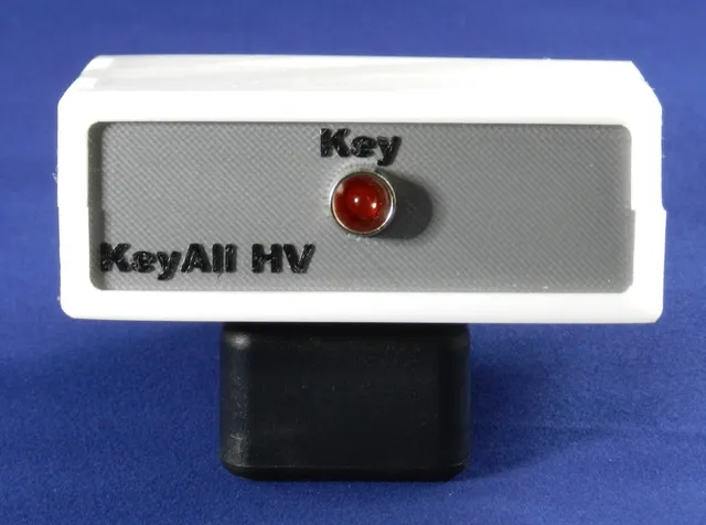
KeyAll HV Case
prusaprinters
From the Jackson Harbor website ( www.wb9kzy.com/keyallhv.htm ): The Keyall HV kit allows the owner of a keyer with a low voltage positive (NPN or n-channel MOSFET) keying transistor to drive the vacuum tube transmitters and transceivers of yesteryear. It comes as a kit on a small PC board, and I needed a case to hold the board, batteries, and connectors. The case was created with the Customizable revised Ultimate Box Maker (https://www.thingiverse.com/thing:2938921). I added an LED to the front to show that the unit is working. I did a filament color change at about just above the 2mm layer to make the text more legible on the front and the back. I'm using PrusaControl as the slicer, and can make the filament change as the text appears. I included a blank panel for those that might need to drill different size holes and/or leave the text or LED off. It works for either the front or the back. I added the snap together, screwless cover design STL files. These cover files provide a cleaner looking final result. It looks like the customizer is working again (18Nov2018), but I have not tried it. It's enabled for anyone who might wish to try. Print Settings Printer Brand: Prusa Printer: i3 MK3 Rafts: No Supports: No Resolution: Case @ 0.2 mm Panels @.15 mm Infill: 20% Filament: Amazon Basics PLA or PETG Notes: Print the panels at a higher resoution made the text look better. Pictures are PLA material. Post-Printing ============= Parts 5 M3x6 flat head countersunk screws (4-40 x 1/4 also work) 2 M3x6 socket head screws (4-40 x 1/4 also work) KetAll HV board 1 2 cell AAA battery holder 7-8 mm thick foam to support under battery holder 1 1/4" stereo jack 1 1/8" mono jack 1 panel mount LED 1 120 ohm 1/4 watt resistor Assembly Tap the 3 feet on the bottom cover for the M3 screws Use 2 M3x6 socket head screws for fastening the KeyAll HV board to the case bottom. Drill and countersink hole in the middle of the battery holder for an M3x6 flathead screw. Place the supporting foam under the battery holder to support the ends of the battery holder. The foam should be thick enough to compress slightly when the battery holder is screwed down. Use an M3x6 Flathead screw to fasten the AAA battery holder to the right hand (viewed from the front) foot. The 1/8" jack goes to the morse code key or keyer. Wire the jack to the KeyAll HV board per KeyAll HV instructions to the keyer output and keyer ground. The 1/4" jack goes to the transmitter. The tip goes to the key line and the sleeve to the ground or common. Wire the jack to the KeyAll HV board per KeyAll HV instructions to the transmitter key input and transmitter ground. The LED anode (longer lead) goes to +3 volts from the battery. The LED Cathode is connected in series with the 120 ohm resistor. Cover in heatshrink tubing and connect the open end of the resistor to the tip of the morse code key/keyer jack. Shrink the heatshrink Install the AAA batteries, the unit can now be tested. Attach a Key , and close it, the LED should light, and if connected to a transmitter, it should key the transmitter. If you printed the Snap (Screwless) cover, place the top cover over the bottom cover and snap closed. If you chose the Screw cover, countersink the holes for the flathead screws on the bottom cover. Tap the holes on the upper cover for the M3 screws. Place the cover on the box, secure with 4 M3x6 Flathead screws. This completes the project. How I Designed This Design decisions. Update 16Dec2018 - At the suggestion of jbebel, I added the snap together, screwless cover design STL files. They work pretty slick, and clean up the box outside, not to mention simplifying construction as there is no need to countersink and tap the cover holes for screws. I used OpenSCAD version 2018.09.05 (git 40af343) to hand edit the .scad file. As I'm new to parametric modeling, this solution was done without adhering to full parametric techniques. I'm still learning. The KeyAll HV has two mounting holes, which left 2 open feet for other uses. One foot was left unused, and the other to mount the battery holder. To place the foot for the battery I used non-parametric offsets in the scad code. Similarly, the text on the panels was set via non-parametric offsets. I used OpenSCAD's gui preview to determine a pleasing to me placement of the text. I added a simple extension to the kit that lights an LED to show that the unit is working, and a sense on the battery condition. It is placed in parallel to the input circuit of the KeyAll HV, and follows the keying of the key/keyer. Category: Electronics
With this file you will be able to print KeyAll HV Case with your 3D printer. Click on the button and save the file on your computer to work, edit or customize your design. You can also find more 3D designs for printers on KeyAll HV Case.