Jet Engine Component; Torque Meter, Planetary Gear type
cults3d
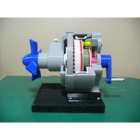
Engines that use rotational output such as Turboprop and Turboshaft incorporate a torque meter system that uses the opposite torque of engine output. There are various methods, but in engines where the engine and reduction gear are integrated, the one utilizing engine oil is often used. By replacing anti-torque with axial movement and adjusting the opening of the valve, it balances pressure in the piston and cylinder with anti-torque axial force. This pressure is then displayed on the cockpit panel as the torque meter and used to control the engine. As a method to generate that axial movement: Planetary gear using spur gears (carrier shaft is as output shaft) add helical spline around ring gear and use axial force generated in ring gear. This method provides relatively large piston area, so engine oil pressure can be used. Planetary gear using helical gears (ring gear is as output shaft) use axial force generated on carrier gear. This method requires higher pressure pump for torque meter because each piston area is narrow. Reduction gear with helical gear train (mainly for turboshaft engines) use axial force generated on intermediate gear. Model of this method will be later. Others some engine use difference in torsion between two or one shaft (hydraulic or electrical). This model reproduces the first method as the cutaway model. The components of this model are: Sun Gear Carrier gear Ring gear with helical spline on outer diameter moves in axial direction Housing with helical spline fixed Piston and cylinder with piston and ring Piston working dimension is about 3 mm. Control valve Oil passage engine oil torque meter oil bleed Brake adjustment screw for operation reproduction and Handle tool By reproducing anti-torque with screw and turning handle, you can see movement of the ring gear piston and valve. In order to operate without oil, the gap between each part is enlarged. For example, piston ring control valve etc. A sponge piece is used instead of spring to allow control valve to follow the piston. Assembly Manual PDF format total 14 pages The detail assembly manual including Parts-List After printing treatment and Assembly procedure are prepared based on Standard Skill Filing Drilling Tapping gluing and tightening. Purchase parts Screws M1.4x3.5L, M2x6L, M2x8L, M3x8L, M3x15L, M4x35L Others φ6 ABS Pipe φ6x25L AL Pipe φ5x10L Spring STL file Total STL files are 26 items including stand and tools Almost of parts are re-designed to this purpose. ws of last two digits of file name means With Support special designed. Total Net Print Time: Approx. 51 HR Estimated as case of PLA, 0.4mm Nozzle, 0.2mm Layer Height, 40% infill and No raft and support Note When at actual print, each parameter may be adjusted by your experience. Printing settings Raft Support Layer Height Infill Depending on your experience My models were printed by idbox using with 0.4 nozzle, 1.75 PLA. I do hope your success!!
With this file you will be able to print Jet Engine Component; Torque Meter, Planetary Gear type with your 3D printer. Click on the button and save the file on your computer to work, edit or customize your design. You can also find more 3D designs for printers on Jet Engine Component; Torque Meter, Planetary Gear type.