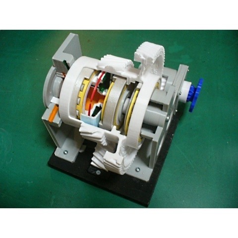
Jet Engine Component; Torque Meter, Helical Gear Train type
cults3d
Engines that harness rotational energy (Turboprop, Turboshaft) incorporate a torque meter system that utilizes the opposite torque of engine output. Various methods are employed, but in engines where the engine and reduction gear are integrated, one method often used involves engine oil. By replacing anti-torque with axial movement and adjusting the opening of the valve, it balances pressure in the piston and cylinder with anti-torque axial force. This pressure is then displayed on the cockpit panel as a torque meter and utilized to control the engine. One method for generating this axial movement involves using a planetary gear system with spur gears, where the carrier shaft serves as the output shaft. A helical spline is added around the ring gear to generate axial force in the ring gear. This method offers a relatively large piston area, making it suitable for engine oil pressure. Another method uses planetary gears with helical gears, where the ring gear serves as the output shaft. Axial force generated on the carrier gear is utilized. However, this method requires a higher-pressure pump due to narrower piston areas. A third method involves reduction gears with a helical gear train, primarily used in turboshaft engines, which utilizes axial force generated on the intermediate gear. Other engines use the difference in torsion between two or one shaft (hydraulic or electrical). This model reproduces the third method as a cutaway model. The components of this model include: Helical Gear Train (Drive Gear, Inter-Gear, Output Gear), Inter-Gear containing Torque Meter Mechanism, Torque Meter Shaft with Piston (Fixed), Torque Meter Cylinder with Control Port (Moving), Bearings: 2 Roller Bearings (for Radial Force), and 1 Ball Bearing (for Axial Force). All bearings are printed except for the Balls. Gearbox Housings support the front and rear of the Torque Meter Shaft, while Oil passage is included for engine oil, torque meter oil, and bleed. However, O-rings are omitted in this model. The Output Gear is cut due to reduced print size and fixation. By turning the Drive Gear, you can observe the movement of the Inter-Gear and Cylinder. Design changes have been made as the oil pressure to move the cylinder backwards cannot be utilized. An Assembly Manual (PDF format, 15 pages) is provided, detailing parts-lists, after-printing treatment, and assembly procedures based on Standard Skills (filing, drilling, tapping, gluing, and tightening). Purchase Parts include all bearings printed except for 8mm Balls, screws of M1.4x6L, M2x10L, and M4x20L. STL files total 28 items including the stand and tools, with "ws" denoting "With Support" in file names. The estimated total net print time is approximately 49 hours for PLA material with a 0.4mm nozzle, 0.2mm layer height, 40% infill, no raft, and support. Printing settings such as Raft, Support, Layer Height, Infill may be adjusted according to individual experience. My models were printed using "idbox" with a 0.4 nozzle and 1.75 PLA material.
With this file you will be able to print Jet Engine Component; Torque Meter, Helical Gear Train type with your 3D printer. Click on the button and save the file on your computer to work, edit or customize your design. You can also find more 3D designs for printers on Jet Engine Component; Torque Meter, Helical Gear Train type.