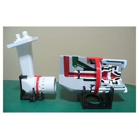
Jet Engine Component; Fuel nozzle, Duplex type
cults3d
It's crucial to burn fuel energy without wasting any of it. The fuel nozzle plays a significant role in this process by being closely linked to the combustion chamber. Its primary function is to provide a stable particle spray across a wide range, from low output to high output. There are several types of fuel nozzles, but the current mainstream is "spray type." Two main types are used: Simplex fuel nozzle and Duplex fuel nozzle. These atomization methods are nearly identical, with the only difference being whether it's single or double. The high-pressure fuel sent from the fuel system is distributed evenly in the nozzle and sprayed through the central injection hole via the swirl passage. Then, compressed air is introduced from the outer periphery of the nozzle to promote atomization, and unburned fuel is blown off when the engine stops to prevent carbon deposition. That's why the duplex fuel nozzle corresponds to an engine that supplies primary fuel and secondary fuel. This model aims to illustrate the basic structure of the "duplex fuel nozzle." The fuel nozzle is closely related to the combustor, but the manufacturing technology is different, so it's manufactured by a specialized manufacturer who specializes in precision parts. Parts with fine and precise holes are assembled in an overwrapping manner, but the surface is super-precision processed (lapped) to prevent leakage between the parts. A key feature of this model is the enlarged cutaway model, which is several times larger than the real thing and made to identify primary and secondary passages by color. This allows for disassembly and assembly, and details such as swirl paths can be confirmed. Another important feature is the overall assembly model, which is half the size of the enlarged cutaway model. The passages from the primary and secondary connectors to the tip are separated. Holes and swirl grooves that affect flow rate and spray pattern are not calculated and designed. Unfortunately, leaks between the passages could not be prevented due to the 3D printer's accuracy. However, it is possible to disassemble and assemble the nozzle parts, and a simple flow test to check if the parts are assembled properly is introduced. In addition, there are "Evaporator Tube type nozzle" and "Centrifugal type," which sprays using centrifugal force from the center of the rotor, used for early engines. Currently, research on new combustors and fuel nozzles is being conducted in various engines to further reduce pollution, and a completely new system will likely emerge. The assembly manual is provided in PDF format, with 12 pages detailing "Parts-List," "After printing treatment," and "Assembly procedure" based on "Standard Skill (Filing, Drilling, Tapping, gluing and tightening)." The download files include STL Files, which are necessary for 3D printing. The file name starts with "ws," indicating that it is designed with support. If you want to perform a water flow test, you will need φ2xID6 and φ3xID22 O-Rings. The total net print time is approximately 43 hours, estimated based on the case of PLA, 0.4mm nozzle, 0.2mm layer height, 40% infill, and no raft or support. Depending on your experience, you can adjust the 3D printing settings such as Raft, Support, Layer Height, and Infill. For parts with threads (Body and Cap), it's recommended to use 0.2mm layer height. If you want to perform a water flow test, it's suggested to use 100% "In Fill" to reduce leaks. I hope you enjoy making this model!
With this file you will be able to print Jet Engine Component; Fuel nozzle, Duplex type with your 3D printer. Click on the button and save the file on your computer to work, edit or customize your design. You can also find more 3D designs for printers on Jet Engine Component; Fuel nozzle, Duplex type.
