Jet Engine Basic Component: Involute Spline
myminifactory
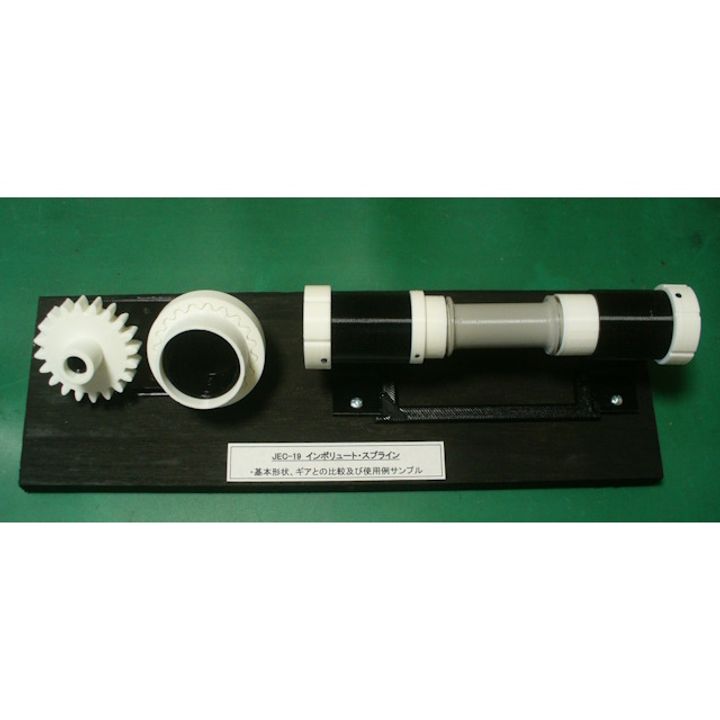
Shaft of the jet engine rotate at high speeds and slide in the axial direction due to temperature differences.When connecting rotating shafts, a structure is required that can maintain the rotation axis even when the torque changes and when it slide.To achieve this goal, "Involute Spline" with teeth that have an involute curve similar to that of gears are used.A pressure angle of 20° is common for gears, but 30° is common for splines, and the tooth height is about half that.The main portion where they are used are between the turbine and compressor rotor, between the turbine rotor and reduction gear, and between the propeller and propeller shaft. The following two types of spline sets have been prepared as sample teaching materials. ① Comparison of gears and splines : Module = 2, number of teeth = 20° ② Example of spline use : Quill shaft between two shafts for the small turbine engine. (Floating type) (can be disassembled and assembled) For the main shaft system of the large engine, a set of two spline shafts is tightened. (Fixed type) And roller bearings are used to relieve axial expansion and contraction.(Shown image only) A. Purchase Parts (None) B. STL file Total STL files are 9 items (Set Parts). C. Total Net Print Time: Approx. 16 HR - (Estimated as case of PLA, 0.4mm Nozzle, 0.2mm Layer Height, 40% infill and No raft and support) Note: When at actual print, each parameter may be adjusted by your experience. D. Printing settings Raft, Layer Height, Infill: Depending on your experience. My models were printed by "idbox" using with 0.4 nozzle, 1.75 PLA. I do hope your success!!
With this file you will be able to print Jet Engine Basic Component: Involute Spline with your 3D printer. Click on the button and save the file on your computer to work, edit or customize your design. You can also find more 3D designs for printers on Jet Engine Basic Component: Involute Spline.
