IR head tracking (Cap Version)
prusaprinters
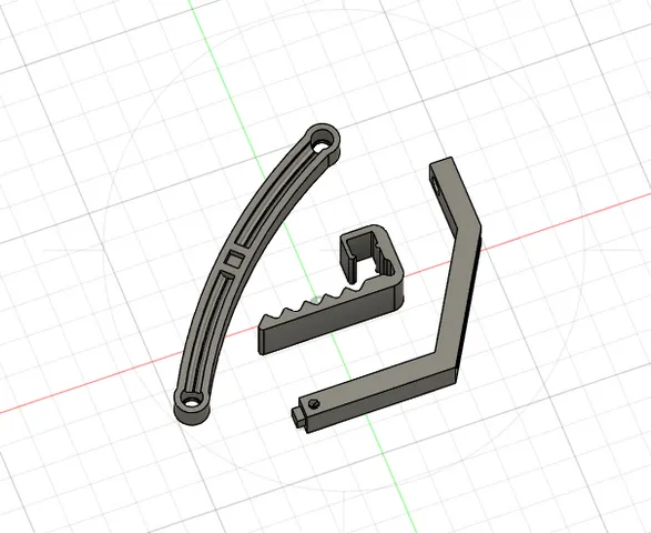
DIY head tracking device intended for cap use. A remix to iTrooper's version https://www.thingiverse.com/thing:707734 Update 03.07.2022Models updated with new dimensions that is close to FreeTrack's suggested hardware dimensions.Only difference is the distance between the two front LEDs (82mm apart instead of 80).Note: These new models are not tested so your mileage may vary Update 23.06.20221.0 Dimensions errorThanks to Brekkis for pointing this out (in the comment section):The head tracking may not work properly when a wide range of motions is demanded. I was testing the original version with Assetto Corsa with very limited up/down and forward/back motion (these motions are not particularly important imho) and it works fine. So if you are playing driving simulation games it may works just fine. I found this reddit thread for Arma https://www.reddit.com/r/arma/comments/1jxuqo/built_my_own_trackir_style_head_tracking_rig_for/?utm_medium=android_app&utm_source=shareand it was suggested that the tracking device follows closely the dimensions stated in this FreeTrack Handbook http://www.free-track.net/fichiers/manuel21en.pdf where:“the LEDs on the bill of the hat should be roughly 140 mm apart, and the single one in the middle should be 100 mm behind the other two, and 80 mm above them”I will be making alterations on this original design to follow closely the suggested dimensions in the future when I got my time on CAD design, but I will need feedbacks for real world testing as I am not gonna be able to fully test them later.2.0 Added link (in Part C of the Instructions) to the awesome DIY guide by Boosted Media for a complete build including the walkthrough for OpenTrack. Design consists of:Body part 1 (push fit) -for two lower IR LEDs housingBody part 2 (push fit)-for the third (upper) IR LEDs housingCap clip for the deviceInstructions:Part A- PrintablesPrint both “Body1” and “Body2” for the electronicsPrint two of the clip for mounting the device on your cap's billPart B- ElectronicsRefer to the attach image diagram for the LED circuit. You may choose to build 4x AAA (in series) for a 6V system or a USB input 5V system. Or if you are like me, I'd choose both with the use of identical connector, refer Item #8 onwards for details.Before you proceed any further, please check your IR LEDs datasheet / specifications for its voltage (or voltage drop per LED) and use this LED calculator to design your circuit: https://ledcalculator.net/Parts needed:SFH485P IR LED x3 (this is what I use https://www.aliexpress.com/item/1005002307235261.html?spm=a2g0o.order_list.0.0.f7de1802AlAuxq)24 AWG wires (for positive & negative)0.3A PTC resettable fuse x1 (x2 if you plan to build dual power choice system)A pair of JST connector x1 (x2 if you plan to build dual power choice system)Bunch of suitable size heat shrink tube6V AAA battery systemAAA battery holder with wires (4 batteries in series) x115 ohms resistor (1/4 watts, +-5%) x15V USB powered systemUSB-A extension cable (1.5 meters long)5.1 ohms resistor (1/8 watts, +-5%) x1If you have noticed, both configurations arranged the LEDs in series connection. This is to allow for easy switching of 6V battery to USB power and vice versa, without any alteration on the wiring side.Caution: Make sure your LEDs polarity is correct before you solder them in place (refer to the manufacturer design drawing for reference).You can use a thin wire (I use fishing line) as a pilot wire to pull your wire through the hole of “Body2”.Once the main wiring (LEDs wiring) is done, you can use some glue to attach both main body parts together, and use the heat shrink tubing to make it looks neat overall.You can leave the connection from the LED circuit open with JST connector (female).For USB powered system -Sacrifice the extension end of the USB cable, and connect the resistor to NEGATIVE side and the PTC fuse to the POSITIVE side of the cut end, and wire them to the appropriate terminal of the JST connector (male) as power source.For AAA battery system - Connect another JST connector (male) to the battery pack as power source with the resistor connected to NEGATIVE side and the PTC fuse connected to the POSITIVE side, in between the JST connector and power pack wiring.Part C- Tracking softwareCheck out this DIY Head Tracking System by Boosted Media https://youtu.be/5Nimz4M-sxU for a full build guide including the walkthrough for OpenTrack software. Print SettingsPrinter Brand:CrealityPrinter: Ender 3 v2Rafts:Doesn't MatterSupports: Touching build plateResolution:0.2Infill: 25%Filament: PLA+ / PLA Pro Notes:0.4mm nozzle
With this file you will be able to print IR head tracking (Cap Version) with your 3D printer. Click on the button and save the file on your computer to work, edit or customize your design. You can also find more 3D designs for printers on IR head tracking (Cap Version).
