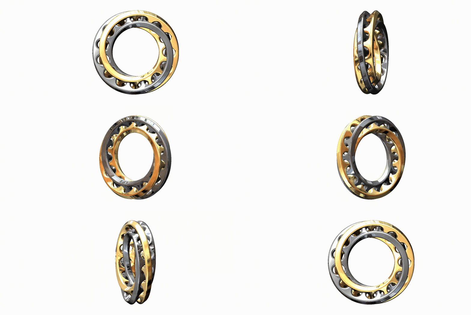
Interlocked Mobius Ring
grabcad
Here is a step-by-step guide to creating your first assembly in SolidWorks. Step 1: Open a New Document To start building your assembly, you'll need to create a new document. Click on "File" and select "New" from the drop-down menu. In the "New Document Properties" window, choose "Assembly" as the document type and click "OK". Step 2: Create the First Component In this tutorial, we'll be creating an assembly of a simple chair. The first component we'll create is the seat. Click on the "Part" tab in the top menu bar and select "Sketch" from the drop-down menu. Draw a circle with a diameter of 10 inches and extrude it to create the seat. Step 3: Create the Second Component Next, we'll create the backrest of the chair. Click on the "Part" tab and select "Sketch" again. Draw a rectangle with dimensions 18 inches by 4 inches and extrude it to create the backrest. Step 4: Add the Components to the Assembly Now that we have our two components, we can add them to the assembly. Click on the "Assembly" tab in the top menu bar and select "Insert Component" from the drop-down menu. Select the seat component and click "OK". Repeat this process for the backrest. Step 5: Mate the Components To assemble the chair, we need to mate the components together. Click on the "Mate" tool in the Assembly tab and select the seat and backrest components. Use the "Fixed" constraint to fix the backrest to the seat. Step 6: Add Fasteners (Optional) If you want to add fasteners to your assembly, you can do so by clicking on the "Fastener" tool in the Assembly tab. Select the type of fastener you want to use and click "OK".
With this file you will be able to print Interlocked Mobius Ring with your 3D printer. Click on the button and save the file on your computer to work, edit or customize your design. You can also find more 3D designs for printers on Interlocked Mobius Ring.
