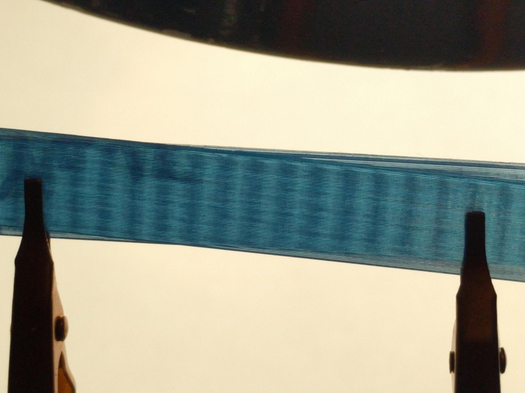
Interference fringe Printer test
thingiverse
Ever wanted to witness printer step or micro step errors firsthand? This is the test for you. Honestly, this test boasts an astonishing level of resolution that far surpasses what a typical printer can handle. In an ideal world, this test would be used to calibrate out position errors and significantly enhance printer accuracy. I recently added a May 2020 STL file to print in vase mode, taking advantage of its cornerless design for faster printing. Additionally, I upgraded my Cetus electronics to Duet2 WIFI electronics, as described here: https://forum.duet3d.com/topic/7709/controlling-a-cetus3d-with-duet3d-0-8-5 The new picture showcases the Duet2 printing the aforementioned STL file. The layers are an impressive 0.15mm thick, which is also the vertical band spacing for calibrating horizontal measurements. My carefully tuned Cetus MK2 with IKO linear rails printed the walls featured in the picture. Each wall has a thickness of 0.3 mm. The edge of each layer forms a cylinder that doubles as a lens, creating a mesmerizing pattern when the two lenses interact. The interference band down the middle exhibits the smallest horizontal errors due to the nearly identical horizontal stepper position and synchronized position errors between the two walls. As you move away from the center, the horizontal position errors become more independent, causing the bands to wobble. Moreover, Z stepper height errors alter the vertical width of the central dark band. Moisture in PLA can create steam, affecting the lens shape, so it's essential to use dry PLA for optimal results. By examining the wall print, you can observe patterns related to timing belt tooth spacing, micro stepper errors, and even extruder filament feed teeth. Any pattern that isn't vertical, horizontal, or parallel to a nearby edge is likely indicative of an issue with the extruder or ball bearing. To further analyze these effects, try printing two walls at once, using translucent PLA, and making sure they're parallel to one horizontal axis. Choose slicer settings to create a hollow center and cut the front and back apart. Place the two front walls in contact with each other, maintaining a few-degree angle between the printed layers. Looking through the two walls will reveal a Moiré pattern similar to the one above. The walls featured in the picture were printed using a 0.4mm nozzle but with a 0.3mm line width and a 0.1mm layer thickness. For more information on this fascinating phenomenon, refer to: https://en.wikipedia.org/wiki/Moiré_pattern This design was created using Fusion 360 by Peter.
With this file you will be able to print Interference fringe Printer test with your 3D printer. Click on the button and save the file on your computer to work, edit or customize your design. You can also find more 3D designs for printers on Interference fringe Printer test.
