InFiDEL Titan
prusaprinters
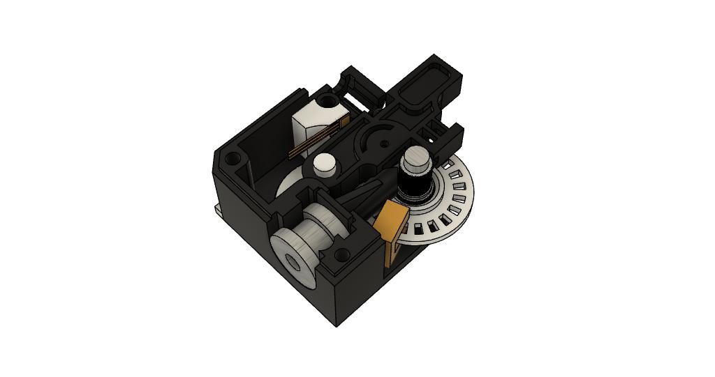
<p>This started as a remix of Tom Sanladerer's InFiDEL sensor but the design was getting too big, it was about the size of an extruder. So I moved on to using a Titan clone as a base for the design, just for a proof of concept.</p><p>There are better designs out there that achieve the same as this. I thought I would share the designs ang my thought on it, so that people can comment and add sugestions that might help others in the future.</p><p>My aim was to add filament distance calculations to the filament diameter measurements of the Inline Filament Diameter by Estimation Lowcost (InFiDEL), but the hobbed bolt of the titan clone defeated the point of the diameter measurements. I ended up with something that will work as a filament runnout sensor giving a low signal if filament is not present. It will also give pulses as filament moves through the sensor so it can be used as a filament jammed sensor just like the BTT smart filament sensor.</p><p>Some of the parts were sourced from a dead inkjet printer and what I had laying around hence the Titan clone and a lot of hot glue. To be honest its very ugly inside but is functional. The electronics are on some perfboard, again very ugly but it works. Originally I was going to use the hobbd bolt and the bearings from the titan and put them into a modified version of Tom Sanladerer's InFiDEL, but as the design was no longer compact I moved on to using the body of the titan instead. I would not recoment trying to recreate this project! As I said earlier “There are better designs out there that achieve the same.”</p><p><strong>Here's some of the issues I encountered along the way.</strong></p><p>As the filament passes through the extruder body it is gripped by the hobbed bolt, which inturn turns the encoder wheel. However the filament passes over a peak on the hobbed bolt then it rests between two peaks. As it does this it pushes the idler and the magnet in and out slightly giving a false reading for filament diameter measurements. It needs to pass through two smooth wheels inorder to give good readings.</p><p>I tried 3d printed replacements but they were not durable enough to be effective.</p><p>I also had issues when testing firmware on the arduino, as the analog read had some ripple on it, giving readings +/- 2bits (then the filament was static nothing was moving through the sensor) even when adding lowpass filters on to the signal from the hall effect sensor and smoothing the data in software. I think this was due to how the Arduino board is designed as the analog reference is tied to the 5v line. I think I might get better results if I try to use the chip on a breadboard instead. as I should get better control over the analog reference.</p><p>As a micro-controller felt extravagnt just to process a signal and output a high or low when a switch does the job in many filament runnout sensors. I ended up using an op-amp setup in comparitor mode. As the magnet get closer to the hall effect sensor in my setup the output from the sensor drops, so the output is connected to the inverting input of the op-amp rather than to the non-inverting input and the voltage divider connected to the non-inverting input. This is the opposite to how this circuit is normally created, if the magnet was the other way round then output from the sensor rises and the normal comparitor setup would work.</p><p><strong>So what's for the furture of this project?</strong></p><p>For the filament diameter reading to work properly it needs to run between two smooth idlers but for the filament distance calculations to work it needs to be gripped inorder to drive the encoder wheel. I have some rubber pinch rollers for a tape cassette players (remember those?) on order, I am hoping the rubber will have the friction to drive the encoder but be smooth enough to not interfere with diameter reading. If this does not work then I will need to extend the housing and seporate the two mechanical functions.</p><p>The encoder can be redesigned to either: </p><p>Use reflective phototransistor rather than a break beam style phototransistor, this sholud make that component more compact.</p><p>OR</p><p>use a magnetic shaft encoderinstead thus removing the need for the encoder wheel.</p><p><strong>Why?</strong></p><p>For me being able to measure how much filament as passed through the extruder can be used as part of a filament management stratagy and if I can get it to be very accruate then it might be the beginning of being able to automate Esteps calibration. </p>
With this file you will be able to print InFiDEL Titan with your 3D printer. Click on the button and save the file on your computer to work, edit or customize your design. You can also find more 3D designs for printers on InFiDEL Titan.