Improved K40 laser cutter Combiner Mount for red dot laser
thingiverse
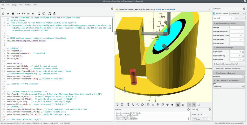
This is my NEW custom K40 Combiner Mount for adding a red dot laser pointer to a K40 laser cutter. It's defaulted to fit the American Photonics(APC) 25mm combiner(link below). To get the customized for where your laser exits from the laser compartment, use the K40 Combiner Mount Test Plug( https://www.thingiverse.com/thing:2915278 ). With it you determine your laser cutter's beam location within the large round hole in the back of the laser cutter. Then use Customizer to set the X and Y positions for this and then select each part and save the STL files. There is also a new fitTest part which will give you a small block with 3 holes in it. The holes are for the combiner, the laser pointer, m3 screw hole. Use adjustment values in Customizer to adjust hole diameters so your 3D printer creates usable parts. Minor Adjustments can be done with the red dot laser by shimming it so it ends up lined up with the same dot a pulse burn produces at your work piece. The default APC Type 2 combiner has 2 m3 screw holes next to the combiner mount. Use 2 8-10mm M3 screws to hold the combiner in place. The Type 1 combiner lens mount consists of a total of 4 screws. Two screws hole the combiner lens mount to the plastic part and the other two screws push the combiner lens mount off of the plastic part. I originally obtained my beam combiner and lens mount from a piece of used equipment. For the APC 25mm combiner you will fit new product here: https://american-photonics.myshopify.com/collections/mark-and-engrave-co2-and-fiber-laser/products/copy-of-15mm-znse-focus-lens-1-5mm-edge-thickness-trotec-speedy-100-by-apc-c02-laser-10-6um?variant=32958753472573 After doing the Combiner Mount Test Plug and 3D printing my parts I first made sure my M3 screws fit the Combiner Mount Plug by pre-fitting. I also made sure the M3 screws passed through but fit tightly to the associated holes in the Combiner Mount. Also see that the 2 alignment pins in the Plug fit in the associated holes in the Combiner Mount. Clean out the 2 thin walls of the laser mount and see that the laser pointer fits snugly in the mount hole. For assembly, I put the Combiner Plug into the hole from the laser tube compartment and used a piece of tape to hold in place. After mounting the red dot laser and the combiner(side marked "IN" faces into the Combiner Mount and towards the laser tube/Mirror #1. I put the 2 M3 screws used to mount the Combiner Mount to the Combiner Plug into the Combiner Mount just enough to hold them. With a hand holding the Plug in place I lined up the top screw on the Combiner Mount with the hole in the Plug and slipped the allen wrench on the screw and turned a few turns. Do the same with the bottom Mount/Plug screw and then tighten them making sure the pins on the Plug are interfacing the Mount. Make sure the red dot laser is at 3 o'clock or 9 o'clock and see if your red dot is showing up on your work surface centered below the lens. Shim or adjust the red dot laser or holder as needed. I added 2 dots of glue on the red dot laser to be sure vibration does not change its position. Test fire your laser to see that your alignment is correct and the red dot and CO2 laser beam are coincident.
With this file you will be able to print Improved K40 laser cutter Combiner Mount for red dot laser with your 3D printer. Click on the button and save the file on your computer to work, edit or customize your design. You can also find more 3D designs for printers on Improved K40 laser cutter Combiner Mount for red dot laser.
