ICE Trike Tracking Adjustment Rods
prusaprinters
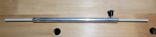
See this video from ICE on how to adjust the tracking (toe-in) of the front wheels on your recumbent trike: https://www.youtube.com/watch?v=2wrX2KVuy7w&t=94sWanting to use something a bit easier to adjust than sticks and rubber bands, I decided to make some measuring rods. The design is similar to what ICE shows in the video, but easier to fabricate. See my attached pictures. I only show the shorter rod. The longer one looks the same.(Apologies to metric users). I bought a 3 foot section of 1/2 inch OD aluminum tubing at the hardware store. I also found some fancy #8 screws with plastic heads, which make it easy to tighten by hand. I also used pieces of an ICE fiberglass flag pole (I had another flag pole). You could use wooden dowel rod instead.For the shorter measuring rod, I cut a 9 inch section of aluminum tubing, and two 5 inch sections of flag pole. The longer rod is 16 inches of tubing and two 10-12 inch sections of flag pole.The inside diameter of the aluminum tubing is much larger than the diameter of the flag pole. I could have used things as is, but I wanted to have a tighter fit, while also centering the flag pole ends in the tubing.I printed some hollow cylinders that fit inside the tubing, and allow the flag pole pieces to slide easily inside. I used the OpenSCAD design from here: https://www.thingiverse.com/thing:45447. The JSON file for the cylinders I made is attached as a zip, as is the STL.Print four inserts, using a brim. In Orca slicer, I also used scarf joints to avoid a seam that would need to be sanded down. I used PLA with 100% infill. PETG would also work.To assemble, insert a printed cylinder into each end of both aluminum tubes. You will need to gently tap them in, as it is purposely a tight fit. The fit on the flag pole is looser, so it slides.If you use a length of 30 mm for the printed inserts as I did, drill a hole about 15 mm in from each end of the tubing. Drill through the aluminum tubing and the cylinder inserts. The hole size depends on what size screws you use. After drilling, use a small round file to take off the burrs on the inside, so the flag pole slides easily.Since only one end needs to be adjustable, I drilled a smaller hole and used a 3 mm screw to secure the non-adjustable flag pole piece. For this end, I drilled into the flag pole as well. If the screw is too loose, add a drop of super glue in the hole.For the adjustable end using the #8 screws with big heads, I used a tap to thread the tubing and the insert. An alternative would be to use self tapping screws. You could print some wing nut adapters for the self tappers to make it easier to tighten them by hand. There are many such designs around.When you need to adjust the adjustable end while setting your toe-in, don't over tighten the screw, or you'll strip the threads. There is no need to go gorilla with this, so with care, it should last a long time.To make it easier to measure the necessary 2 mm toe-in, I'm going to print a 2 mm spacer.
With this file you will be able to print ICE Trike Tracking Adjustment Rods with your 3D printer. Click on the button and save the file on your computer to work, edit or customize your design. You can also find more 3D designs for printers on ICE Trike Tracking Adjustment Rods.