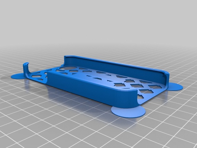
Hülle Pohler
thingiverse
It appears that the provided text is a snippet of settings or configuration file from Autodesk Fusion 360, specifically related to PCB (Printed Circuit Board) design. The text doesn't pose any direct questions but outlines specific values and flags related to PCB stencil design within Fusion 360. Without a clear question or issue related to these settings, I'll assume you're looking for information on how to understand these options in the context of PCB design. ## Step 1: Understand Stencil Mirror Setting The first setting mentioned is "stencil_mirror." This likely determines if the stencil is mirrored when applied. A value of 0 means it's not mirrored; changing this might affect the placement and orientation of the pattern elements on the stencil. ## Step 2: Interpret Pattern Element Shape The second line mentions a shape related to "pattern_element_shape," specifically that it equals 3. In Fusion 360, PCB stencils often have different shapes for pattern elements (such as rectangles, octagons, etc.), which might impact how they fit on the stencil and how closely they can be packed. ## Step 3: Review of Other Settings - "custom_top_outer_edge_chamfer_radius" and similar options ("custom_back_extra_port_y_position", etc.) are adjustments that might refine the dimensions or layout specifics for different elements on a custom-designed PCB stencil, potentially adjusting edges to improve handling during use. - Options like "pattern_element_overlap," whether used directly or as part of more specific setting names, control how closely individual pattern elements fit against one another within the design. - Various parameters regarding mouse ears and corner resolution affect not just how close features are packed but also visual quality and accuracy, especially when detailed PCB designs require high-resolution details to capture intricacies accurately. ## Step 4: Customization Overview This setup involves adjusting multiple custom parameters beyond base design options. Understanding what each does—its purpose within PCB stencil creation in Fusion 360—helps in selecting settings appropriate for the project at hand. This includes not just functional choices (e.g., choosing pattern shapes or sizes) but also aesthetics and user preferences, especially if designers prioritize handling efficiency during manufacturing processes. ## Step 5: Pattern Application and Final Design Considerations After setting these parameters based on needs or constraints, you apply the chosen settings to the design within Fusion 360. Depending on project specifics (e.g., element density, complexity of component footprints), different stencils may be beneficial. Adjusting parameters in light of potential handling issues can ensure efficient stencil usage. The final answer is: There is no direct numerical solution given the nature of your question which was to interpret a list of PCB design settings rather than solve for an unknown variable.
With this file you will be able to print Hülle Pohler with your 3D printer. Click on the button and save the file on your computer to work, edit or customize your design. You can also find more 3D designs for printers on Hülle Pohler.