Hélice quadri-pales orientables
prusaprinters
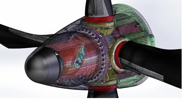
Voici un remix de l'hélice quadri-pales orientables pour le turboprop (https://www.thingiverse.com/thing:3014536) de Konchan77 qui fonctionne. En effet, sa version avec pignons droits ne peut pas fonctionner ; il faut nécessairement utiliser des pignons coniques. Ce remix utilise donc des engrenages coniques et un système de commande d'orientation des pales intégré dans le cône d'hélice. Le nez du cône constitue le bouton de commande que l'on peut tourner dans un sens ou dans l'autre pour obtenir l'angle d'incidence des pales qu'il convient (de la mise en drapeau à l'inversion de poussée). L'ensemble est composé de trois parties : Bloc arrière du cône regroupant : Les pales et leurs pignons coniques. La roue-fourreau conique et sa butée à bille. La plaque arrière et sa fixation sur l'arbre de sortie PV du turboprop. Bloc central regroupant le mécanisme d'orientation des pales constitué par : Le fourreau à double rampe hélicoïdale de la roue conique (partie émergente du bloc arrière). Le piston et ses deux roulements-guides. Bloc avant constitué par : Le cône d’extrémité qui par sa rotation orientera les pales. La vis-mère. Le montage de l'ensemble se fera dans cet ordre : Les pales. Le bloc arrière et éventuellement sa fixation sur le turboprop. Le bloc central avec le bloc avant. On y reviendra en détail dans la section "Montage". J'attire votre attention sur la précision de ce montage. L’ajustement de nombreuses pièces est au 1/10mm. Cela nécessite donc pour votre imprimante une calibration parfaite, des réglages parfaitement maîtrisés et l'usage de filaments de qualité. Comme pour la réalisation du turboprop de konchan77, ce montage n'est pas pour les novices et nécessite rigueur et précision. Vous ne serez pas décu du résultat ;o) Here is a remix of the quadruple-directional propeller for Konchan77's turboprop (https://www.thingiverse.com/thing:3014536) which works. Indeed, its version with spur gears cannot work; it is necessary to use bevel gears. This remix therefore uses bevel gears and a blade orientation control system integrated in the propeller cone. The nose of the cone is the control knob that can be rotated in either direction to obtain the appropriate blade angle of incidence (from feathering to thrust reversal). The set is composed of three parts: Rear block of the grouping cone: The blades and their bevel gears. The tapered sleeve wheel and its ball bearing. The rear plate and its mounting on the turboprop PV output shaft. Central block containing the blade orientation mechanism consisting of: The double spiral ramp sleeve of the bevel gear (emerging part of the rear block). The piston and its two guide bearings. Front block made up of: The end cone which by its rotation will orient the blades. The lead screw. The assembly will be done in this order: The blades. The rear block and possibly its attachment to the turboprop. The central block with the front block. We will come back to this in detail in the "Assembly" section. I would like to draw your attention to the accuracy of this assembly. The adjustment of many parts is 1/10mm. This requires perfect calibration, perfectly controlled settings and the use of quality filaments for your printer. As with the production of the konchan77 turboprop, this assembly is not for novices and requires rigour and precision. You will not be disappointed with the result ;o) Translated with www.DeepL.com/Translator Print Settings Printer: ATOM 2.0 - Wanhao D7 v1.5 Box Rafts: No Supports: Yes Resolution: 100 - 150 µm Infill: 25 - 100% Filament: Verbatim - eMotionTech PLA Couleurs : voir photos Nomenclature ============ Voici la liste des pièces (la quantité) et les liens URL : Roulement MR105ZZ 5x10x4 (4) : https://www.ebay.fr/itm/ROULEMENT-A-BILLES-1pc-MR105ZZ-MR115ZZ-688ZZ-608ZZ-6701ZZ-6700ZZ-MR106ZZ-MR85ZZ/360743440586?hash=item53fdfc10ca:m:mDgiDBgPg5TM1eI9KPeh3fQ Roulement MR84ZZ 4x8x3 (2) : https://www.ebay.fr/itm/10pcs-lot-MR84ZZ-4X8X3mm-miniature-deep-groove-Ball-Bearings-MR84-L-840ZZ/112485580266?ssPageName=STRK%3AMEBIDX%3AIT&_trksid=p2060353.m1438.l2649spm=a2g0s.9042647.6.2.sfCbru&orderId=505432364990379&productId=32732251384 Bille acier diam 3mm (33) : https://www.ebay.fr/itm/Roulement-Billes-Haute-Qualite-En-Acier-Inoxydable-Precision-2mm-16mm-10-5000PCS/182998675674?hash=item2a9b9230da:m:moob6smzKvjAVSlRyFN6Q7g:rk:2:pf:0 Vis TCHC M1.4x3 A4 (8) : https://www.cergy-vis.fr/tchc-m1-4x3-inox-a4-ef-din-912.html Vis TCHC M1.4x4 A4 (4) : https://www.cergy-vis.fr/tchc-m1-4x4-inox-a4-ef-din-912.html Tube alu 4x9 (2) : https://hobbyking.com/en_us/round-alum-tube-4mm-od-x-45mm.html Here is the list of parts (quantity) and URL links: Bearing MR105ZZ 5x10x4 (4) : https://www.ebay.fr/itm/ROULEMENT-A-BILLES-1pc-MR105ZZ-MR115ZZ-688ZZ-608ZZ-6701ZZ-6700ZZ-MR106ZZ-MR85ZZ/360743440586?hash=item53fdfc10ca:m:mDgiDBgPg5TM1eI9KPeh3fQ Bearing MR84ZZ 4x8x3 (2): https://www.ebay.fr/itm/10pcs-lot-MR84ZZ-4X8X3mm-miniature-deep-groove-Ball-Bearings-MR84-L-840ZZ/112485580266?ssPageName=STRK%3AMEBIDX%3AIT&_trksid=p2060353.m1438.l2649spm=a2g0s.9042647.6.2.sfCbru&orderId=505432364990379&productId=32732251384 Steel ball diam 3mm (33) : https://www.ebay.fr/itm/Roulement-Billes-Haute-Qualite-En-Acier-Inoxydable-Precision-2mm-16mm-10-5000PCS/182998675674?hash=item2a9b9230da:m:moob6smzKvjAVSlRyFN6Q7G:rk:2:pf:0 TCHC Screw M1.4x3 A4 (8): https://www.cergy-vis.fr/tchc-m1-4x3-inox-a4-ef-din-912.html TCHC Screw M1.4x4 A4 (4): https://www.cergy-vis.fr/tchc-m1-4x4-inox-a4-ef-din-912.html Aluminium tube 4x9 (2) : https://hobbyking.com/en_us/round-alum-tube-4mm-od-x-45mm.html Translated with www.DeepL.com/Translator Montage Nota : j'ai réalisé mes collages PLA avec du chloroforme ou du dichlorométhane (chlorure de méthylène). Ces collages sont de véritables soudures comme avec l'acétone pour l'ABS. Utilisez un masque respiratoire et assurez une ventilation efficace de votre local. 1 - Montage des pales (Fig. 1) A répéter pour chaque pale. Coller le bord d'attaque renforcé (New-Blade102.stl) sur la pale (New-Blade102CCW.STL). Coller la clavette (ClavetteP01.STL) sur le pignon conique 18 dents (Pignon_con_18T.STL). Glisser l'anneau de pied de pale sur le pignon conique. Il doit tourner librement. Coller la pale sur son pignon en veillant que le repère sur le pignon soit vers vous et que le bord d'attaque renforcé de la pale soit vers le bas. Insérer le roulement MR105ZZ dans l'alésage prévu. 2 - Montage du bloc arrière Fig. 2 Mettre en place les billes (D3mm) sur le chemin de roulement du demi-carter arrière (Spinner-BodyP402.STL). Glisser la roue conique 32 dents (Roue_con_32T.STL) jusqu’à ce qu'elle vienne reposer sur les billes. Sa rotation doit libre et fluide (sans point dur). Meuler si besoin son chemin de roulement afin d'obtenir une surface de roulement correcte. Fig. 3 Réunir les pales sur le hub (Spinner-BladeP04.STL) en positionnant les repères sur pignon vers vous. Positionner cet ensemble sur la roue conique en alignant son repère (sur le fourreau) avec un repère d'un des pignons. Vous assurez ainsi la bonne position des rampes hélicoïdales du fourreau par rapport la position des pales (le pas). Une fois ce réglage délicat fait, la pale qui vous a servi de repère constitue "la pale de référence" et l'ensemble est réglé en position "Pas nul". Fig. 4 Coller le fond-coupleur (Spinner-Hub201.stl) au demi-carter arrière (Spinner-Body02a.STL). Fig. 5 Assembler les deux demi-carter. Contrôler la rotation sans point dur des pales. Visser les 4 vis TCHC M1.4x4. Le bloc arrière est assemblé ;o) Fig. 6 Si vous souhaitez monter cette hélice sur le turboprop, c'est le moment. L'axe PV devra être tarauder M3 au préalable. + Emmancher le bloc arrière sur l'axe PV cannelé du turboprop. + Insérer la rondelle épaulée d'appui dans le fourreau. + Fixer l'ensemble à l'aide de la vis M3 (TBHC M3x10 par ex.). 3 - Préparation du bloc central Fig. 7 Assembler les différents éléments du piston (Piston.STL). Fig. 8 Mettre en place le piston dans les glissières du carter central (Spinner-Body03.STL). Poussez-le en fond de glissières. 4 - Préparation du bloc avant Fig.9 Coller la vis-mère (VisPas.STL) dans le nez de cône d'hélice (Spinner-CapP01.STL). 5 - Assemblage bloc avant/bloc central Fig.10 Visser à fond le bloc avant dans le piston. Le nez de cône d'hélice (Spinner-CapP01.STL) doit venir s'emmancher dans le carter central (Spinner-Body03.STL) sans point dur. 6 - Assemblage final Fig.11 Mettre les pales "en drapeau" : tourner le fourreau dans le sens anti-horaire jusqu’à aligner son repère avec les vis de fixation du bloc arrière. Présenter le bloc avant-central en respectant l'alignement de tous les repère conformément à la figure 11. Les roulements du piston doivent s'engager dans leur rampe sans forcer. Emboîter le carter central dans le bloc arrière. Parfaire l'alignement du carter central en alignant les trous de vis. Fig.12 Visser les 4 vis TCHC M1.4x3 du nez de cône d'hélice. Contrôler l'ensemble de la cinématique en dévissant jusqu’à la position "Inversion de flux" et en vissant jusqu'à la position "En drapeau". Il ne doit pas y avoir de points durs. Visser les 4 vis TCHC M1.4x3 solidarisant le carter central et le bloc arrière. Fig. 13 Ouuuffff !!! C'est fini ;o) Note: I made my PLA collages with chloroform or dichloromethane (methylene chloride). These adhesives are real welds as with acetone for ABS. Use a respirator and ensure effective ventilation of your room. 1 - Mounting the blades (Fig. 1) To be repeated for each blade. Glue the reinforced leading edge (New-Blade102.stl) to the blade (New-Blade102CCW.STL). Glue the key (KeyP01.STL) to the 18-tooth bevel gear (Gear_con_18T.STL). Slide the blade foot ring onto the bevel gear. It must rotate freely. Glue the blade to its pinion, making sure that the mark on the pinion is towards you and that the reinforced leading edge of the blade is downwards. Insert the MR126ZZ bearing into the bore provided. 2 - Mounting the rear block Fig. 2 Place the balls (D3mm) on the raceway of the rear half-case (Spinner-BodyP402.STL). Slide the 32-tooth bevel gear (Wheel_con_32T.STL) until it rests on the balls. Its rotation must be free and fluid (without hard point). If necessary, grind the raceway to obtain a correct running surface. Fig. 3 Assemble the blades on the hub (Spinner-BladeP04.STL) by positioning the pinion markers towards you. Position this assembly on the bevel gear by aligning its mark (on the sleeve) with a mark on one of the pinions. This ensures that the helical ramps of the sheath are in the correct position in relation to the position of the blades (pitch). Once this delicate adjustment has been made, the blade you used as a reference is called the "reference blade" and the assembly is set to the "Not zero" position. Fig. 4 Glue the bottom coupler (Spinner-Hub201.stl) to the rear half box (Spinner-Body02a.STL). Fig. 5 Assemble the two half-cases. Check the smooth rotation of the blades. Screw in the 4 TCHC M1.4x4 screws. The rear block is assembled ;o) Fig. 6 If you want to mount this propeller on the turboprop, now is the time. The PV axis must first be tapped M3. + Slide the rear block onto the fluted PV axis of the turboprop. + Insert the shoulder washer into the sleeve. + Secure the assembly with the M3 screw (e. g. TBHC M3x10). 3 - Preparation of the central block Fig. 7 Assemble the different piston elements (Piston.STL). Fig. 8 Insert the piston into the slides of the central housing (Spinner-Body03.STL). Push it into the bottom of the slides. 4 - Preparation of the front block Fig. 9 Glue the lead screw (VisPas.STL) into the propeller cone nose (Spinner-CapP01.STL). 5 - Front block/central block assembly Fig. 10 Screw the front block fully into the piston. The propeller cone nose (Spinner-CapP01.STL) must fit into the center housing (Spinner-Body03.STL) without hard point. 6 - Final assembly Fig.11 Set the blades "feathered": turn the sheath counter-clockwise until its mark is aligned with the fastening screws of the rear block. Present the front center block in accordance with the alignment of all markings as shown in Figure 11. The piston bearings must engage in their ramp without forcing. Insert the central housing into the rear block. Perfect the alignment of the central housing by aligning the screw holes. Fig. 12 Screw in the 4 TCHC M1.4x3 screws of the propeller cone nose. Check the entire kinematics by unscrewing to the "Flow Reversal" position and screwing to the "Flagging" position. There must be no hard points. Screw on the 4 TCHC M1.4x3 screws securing the central housing and the rear block. Fig. 13 Ouuuffff!!!!! It's over ;o) Translated with www.DeepL.com/Translator Update 2018/12/14 : Mise à jour de la section Nomenclature. Ajout référence bille acier diam 3mm et lien URL 2019/07/18 : Mise à jour de la section Nomenclature. remplacement de la référence des roulements MR126ZZ 6x12x4 par des MR105ZZ (5x10x4) Correction de la Fig.1 Category: Engineering
With this file you will be able to print Hélice quadri-pales orientables with your 3D printer. Click on the button and save the file on your computer to work, edit or customize your design. You can also find more 3D designs for printers on Hélice quadri-pales orientables.