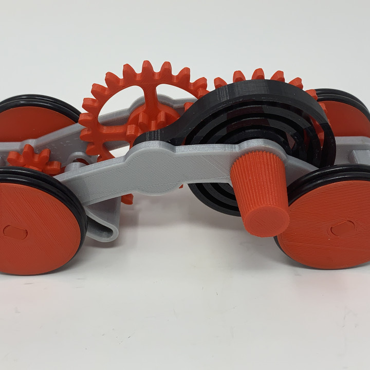
How I Designed a 3D Printed Windup Car Using Autodesk Fusion 360.
myminifactory
I've Designed a 3D Printed Windup Car Using Autodesk Fusion 360 Designing a windup car can be a fun project, especially when using 3D printing technology. I've created a four-part video series detailing how to design this 3D printed windup car with a floating pinion drive using Autodesk Fusion 360. The design process starts with designing the chassis, which consists of two frames: "Frame, Right.stl" and "Frame, Left.stl." To gain additional ground clearance, the gear train layout is modified in this video. The PLA spring motor and gear train components are then used to assist with laying out the right frame. Next, the left frame is created by projecting the right frame profile and modifying the various socket and crossmember profiles to allow mating of the two frame sides. The axles and wheels are designed in a separate step. There are two unique axles: "Axle, Gear, Floating.stl" and "Axle.stl," and one unique wheel: "Wheel.stl." After centering the car assembly, the rear axle is designed and then copied and pasted to create the front axle. The floating pinion axle is designed and positioned, followed by the design of the wheels. The wheel is designed, then copied and pasted to create the remaining wheels. To test the math, I fully wound the PLA spring motor, held the car firmly on a smooth surface along side an extended tape measure, then moved the car forward by hand noting that the floating pinion gear indeed disengaged the PLA spring motor from the drive axle at exactly 5'6" (ok, math isn't that bad after all). The total gear ratio from the PLA spring motor to the drive axle is 1:9 (drive to driven), using two gear stages of 1:3 each. This results in for each rotation of the spring motor, the drive axle will rotate nine times. Thus with a wheel diameter of 47.5mm, the distance the car will travel under spring power is approximately: (pi * wheel diameter) * 1.25 * 9 = 1678.788574262046mm = 5.5 feet, where: (pi * wheel diameter) = wheel circumference = 149.2256510455152mm, 1.25 is the number of winds of the PLA spring motor knob, hence the number of times the PLA spring motor will rotate (discounting friction loss and failure to remove the build plate "ooze"), 9 is the total gear ratio from the PLA spring motor to the drive axle (again, drive to driven). To test the math, I fully wound the PLA spring motor, held the car firmly on a smooth surface along side an extended tape measure, then moved the car forward by hand noting that the floating pinion gear indeed disengaged the PLA spring motor from the drive axle at exactly 5'6" (ok, math isn't that bad after all). The design process is detailed in four videos: Designing the Chassis: https://www.youtube.com/watch?v=k0e-XgTPnS8 Designing the Axles and Wheels: https://www.youtube.com/watch?v=ZS41pWYm3Rs
With this file you will be able to print How I Designed a 3D Printed Windup Car Using Autodesk Fusion 360. with your 3D printer. Click on the button and save the file on your computer to work, edit or customize your design. You can also find more 3D designs for printers on How I Designed a 3D Printed Windup Car Using Autodesk Fusion 360..
