Horia Jeweling Tool Spindle Changing Support
prusaprinters
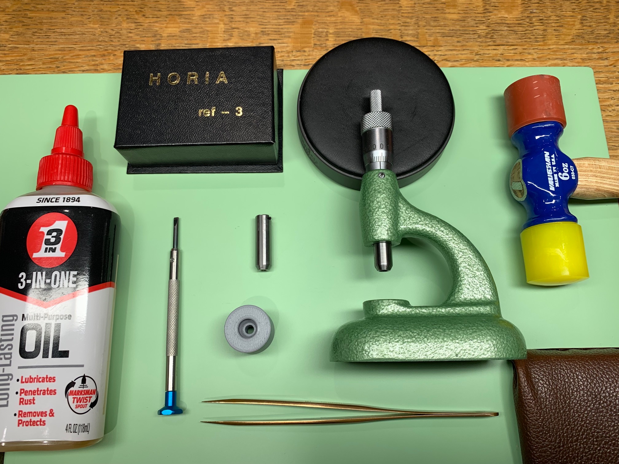
<p>Horia jeweling tools come with either 3mm or 4mm replaceable spindles; this support aides in the process of changing them out. The support features 2 ends: one contains a simple taper, the other is slightly more recessed with a flat and taper. A hole in the center ensures that the interior portion of the spindle is not damaged during the removal process.</p><p>For reference, the Horia jeweling tools go by part #PO 61, PO 61-1, or Bergeon part #5372-61. The spindles are Horia part #61-02 (must specify 3mm or 4mm) or Bergeon part #5372-61-B3 for 3mm, Bergeon 5372-61-B4 for 4mm. </p><p>I recommend printing this model with the simple tapered end facing down towards the print bed. This avoids any issues with overhangs. Once printed, test the spindle tips in both ends. The spindles should enter and exit without getting stuck. Tolerances are pretty close with the model so if your spindle gets stuck, enlarge in PrusaSlicer by a couple percentage points. </p><p>This model has been tested on the Prusa i3 MK3S+ and Mini+ with a 0.40mm nozzle at 0.15mm and 0.20mm layer heights.</p><p>The examples in the photos are printed using Overture Matte Light Gray PLA.</p><p><strong>How to switch out the spindle in your Horia Jeweling Tool:</strong></p><figure class="image image-style-align-center image_resized" style="width:75%;"><img src="https://media.printables.com/media/prints/231363/rich_content/3da3897e-c6da-413c-9688-f47298824f05/img_4697.jpg#%7B%22uuid%22%3A%22a2e2b077-edf6-4fa5-aeb4-e69050b1024f%22%2C%22w%22%3A2016%2C%22h%22%3A1512%7D"></figure><p>You will need:</p><ol><li>Horia jeweling tool</li><li>Replacement Horia tool spindle</li><li>3D-printed Horia tool spindle support</li><li>250 Screwdriver (2.5mm width)</li><li>Tweezer</li><li>Small soft-sided hammer (rubber, nylon, rawhide, etc.)</li><li>(Optional) Multi-purpose oil for extra lubrication</li><li>(Optional) Horia jeweling tool bits to test fit</li></ol><p>First, remove the set screw near the top of the base using the 250 screwdriver. Sometimes this set screw can be very tight, so make sure your screwdriver blade is sized correctly to avoid damaging the screw slot. I did not see any Loctite/threadlocker applied to these set screws, so you should not need to use heat to loosen them up. </p><figure class="image image_resized" style="width:50%;"><img src="https://media.printables.com/media/prints/231363/rich_content/10b5c027-e89c-486e-afed-3014a991ad03/img_4674.jpg#%7B%22uuid%22%3A%224db14424-4607-4767-aa6d-45f2006727ed%22%2C%22w%22%3A1512%2C%22h%22%3A2016%7D"></figure><p>Remove set screw with tweezer and set aside for later.</p><figure class="image image_resized" style="width:50%;"><img src="https://media.printables.com/media/prints/231363/rich_content/5f280e8c-9ef5-42dc-9189-d6a9f36e9c10/img_4675.jpg#%7B%22uuid%22%3A%2229bd0c5e-ae7f-4937-a8b8-11df65d4f1a6%22%2C%22w%22%3A2016%2C%22h%22%3A1512%7D"></figure><p>Now, you can place the 3D-printed spindle support on the base, centered directly below the spindle. I recommend using the shallower end (tapered-only side) first. If you find the spindle is not budging during the removal process, then try the deeper end (flat & tapered side). </p><figure class="image image_resized" style="width:50%;"><img src="https://media.printables.com/media/prints/231363/rich_content/d979cb29-d409-46fb-a0ff-4e9087c1d085/img_4677.jpg#%7B%22uuid%22%3A%22703161a3-a431-4310-8162-a127c07ee595%22%2C%22w%22%3A1512%2C%22h%22%3A2016%7D"></figure><p>(Shallow, tapered side)</p><figure class="image image_resized" style="width:50%;"><img src="https://media.printables.com/media/prints/231363/rich_content/c948cded-e9f2-417b-89fb-4c780ff4db45/img_4694.jpg#%7B%22uuid%22%3A%22541691b0-7d49-4fa6-b31d-2659e89ba862%22%2C%22w%22%3A1512%2C%22h%22%3A2016%7D"></figure><p>(Deeper, flat & tapered side)</p><p>Turn the Horia tool handle so that it lowers the spindle down towards the support. The support will self-center to match the spindle. Eventually, the spindle will bottom out on the support. </p><figure class="image image_resized" style="width:50%;"><img src="https://media.printables.com/media/prints/231363/rich_content/2c9428b4-3f9c-4fdc-89ce-f1bc4b883c43/img_4678.jpg#%7B%22uuid%22%3A%226f81eb4c-5b74-451f-aa7f-f9d9befe237a%22%2C%22w%22%3A2016%2C%22h%22%3A1512%7D"></figure><figure class="image image_resized" style="width:50%;"><img src="https://media.printables.com/media/prints/231363/rich_content/bbee9474-f323-4b4e-a1a6-745fbc894323/img_4679.jpg#%7B%22uuid%22%3A%228415a90b-d4c9-44fe-9d79-f9aa93109f3e%22%2C%22w%22%3A2016%2C%22h%22%3A1512%7D"></figure><p>(Spindle lowered into position)</p><p>The scary part! Keep turning the handle so that the spindle forces itself off of the base. You should see the spindle and handle assembly start to lift up. If it feels like you are turning with too much force, you may want to back off and switch to the other end of the 3D-printed support (flat & tapered). </p><figure class="image image_resized" style="width:50%;"><img src="https://media.printables.com/media/prints/231363/rich_content/332dd2f5-71f3-4aa8-8750-67daabbce1a2/img_4681.jpg#%7B%22uuid%22%3A%2261927535-8198-4e55-ab77-cb276b58b5c1%22%2C%22w%22%3A1280%2C%22h%22%3A959%7D"></figure><p>(Flush with base)</p><figure class="image image_resized" style="width:50%;"><img src="https://media.printables.com/media/prints/231363/rich_content/53e03b9a-5888-464d-8fdd-d339279323d4/img_4682.jpg#%7B%22uuid%22%3A%221e6b1b35-7472-435f-ba86-1a8a988799bf%22%2C%22w%22%3A1280%2C%22h%22%3A959%7D"></figure><p>(Lifted up from base)</p><p>Hooray! The spindle and handle assembly has come loose. Note that there is a circular recess in the assembly that lines up with the set screw. </p><figure class="image image_resized" style="width:50%;"><img src="https://media.printables.com/media/prints/231363/rich_content/ed6a3a64-5f88-461b-acf5-5822535285f7/img_4683.jpg#%7B%22uuid%22%3A%2227dcaf1e-2364-4028-9bbd-11a8d73e9376%22%2C%22w%22%3A959%2C%22h%22%3A1280%7D"></figure><p>Swap out the old spindle for the new spindle.</p><figure class="image image_resized" style="width:50%;"><img src="https://media.printables.com/media/prints/231363/rich_content/d707ff7e-fcdc-4fae-9407-24006b482424/img_4684.jpg#%7B%22uuid%22%3A%22e7866c41-affc-45d0-b2f0-d6d80884afc1%22%2C%22w%22%3A2016%2C%22h%22%3A1512%7D"></figure><p>Optional: You may want to add a little lubrication to parts of the assembly to keep the action smooth. </p><p>We are ready to re-install the spindle and handle assembly. Note the correct orientation. The notch in the spindle should be facing towards the front. Remember, the set screw recess should be aligned on the same side as the set screw opening in the base.</p><figure class="image image_resized" style="width:50%;"><img src="https://media.printables.com/media/prints/231363/rich_content/75ceacc4-ccf1-4f30-bc20-5f5d37f1cf54/img_4696.jpg#%7B%22uuid%22%3A%2275d3485a-f3d6-43b5-95f6-6d6cde662abc%22%2C%22w%22%3A2016%2C%22h%22%3A1512%7D"></figure><p>(Spindle notch)</p><figure class="image image_resized" style="width:50%;"><img src="https://media.printables.com/media/prints/231363/rich_content/3821db35-d726-4350-9bf4-397eaa1e59c8/img_4686.jpg#%7B%22uuid%22%3A%22ab57736a-710b-4917-bc4c-68e56f052b77%22%2C%22w%22%3A959%2C%22h%22%3A1280%7D"></figure><p>(Correct alignment of handle)</p><p>As it took some force to remove the spindle and handle assembly from the base, we will need to add some force to put it back into position. Once you are sure the alignment is correct, take the soft mallet/hammer and tap the very top of the handle. This will push the assembly down into the base. </p><figure class="image image_resized" style="width:50%;"><img src="https://media.printables.com/media/prints/231363/rich_content/6399296d-7c33-4433-bc54-62742b9100a5/img_4687.jpg#%7B%22uuid%22%3A%226537b6e4-4de7-4ae7-9512-69834506b1db%22%2C%22w%22%3A1512%2C%22h%22%3A2016%7D"></figure><p>Start with gentle taps, then increase the force as needed. Pressure should be applied downwards and not laterally; you do not want to bend the handle tip. You should see the assembly come flush with the base. Once it is flush, STOP hammering!</p><figure class="image image_resized" style="width:50%;"><img src="https://media.printables.com/media/prints/231363/rich_content/f8ae9656-5987-4f8a-99d8-af4ea5ace2f4/img_46881.jpg#%7B%22uuid%22%3A%22e423c0fa-e72d-4219-8f40-006b18b5d983%22%2C%22w%22%3A959%2C%22h%22%3A1280%7D"></figure><p>(Gap visible between the top of the base and the bottom of the handle = keep on tapping!)</p><figure class="image image_resized" style="width:50%;"><img src="https://media.printables.com/media/prints/231363/rich_content/df4d3bd3-af1c-4afe-a427-402532ed310e/img_4690.jpg#%7B%22uuid%22%3A%22b2ba2ec5-589a-455c-9686-c9c8fbdc07ab%22%2C%22w%22%3A959%2C%22h%22%3A1280%7D"></figure><p>(Little to no gap visible between top of base and bottom of handle = you're done!)</p><p>Reinstall the set screw using the tweezer and screwdriver.</p><figure class="image image_resized" style="width:50%;"><img src="https://media.printables.com/media/prints/231363/rich_content/cbfc4f82-833f-47a6-a4a0-7f1bcbe12f6b/img_4691.jpg#%7B%22uuid%22%3A%222e29293f-f01c-48df-8784-a7b53a5ccb12%22%2C%22w%22%3A2016%2C%22h%22%3A1512%7D"></figure><p>Check the function of the Horia jeweling tool. Turn the handle in both directions; the spindle should move freely up and down without resistance. I recommend turning it all the way to the minimum and maximum positions. </p><p>Congrats, you have now changed out the spindle on your Horia tool and made it more useful!</p><figure class="image image_resized" style="width:75%;"><img src="https://media.printables.com/media/prints/231363/rich_content/dce21de8-a078-4255-a96a-7013a930f922/img_4695.jpg#%7B%22uuid%22%3A%22bdbd3932-4c2c-440d-a00c-279d2ea44dd2%22%2C%22w%22%3A2016%2C%22h%22%3A1512%7D"></figure><p> </p><p> </p>
With this file you will be able to print Horia Jeweling Tool Spindle Changing Support with your 3D printer. Click on the button and save the file on your computer to work, edit or customize your design. You can also find more 3D designs for printers on Horia Jeweling Tool Spindle Changing Support.