Hole size calibration
thingiverse
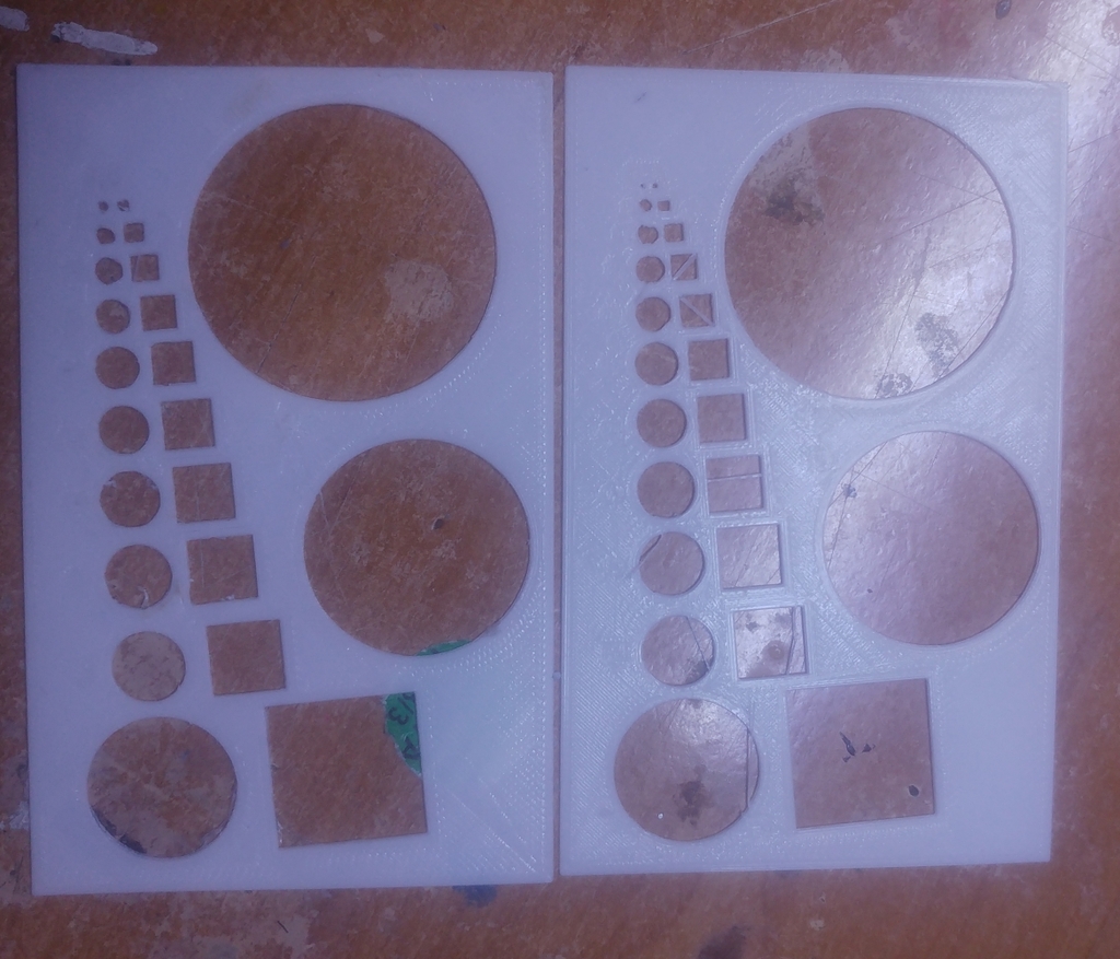
This is a test print for determining hole size adjustment. The goal is to solve a problem that arises when calibrating printers for accurate external dimensions - the holes are often too small. Several factors can contribute to this issue, including incorrect handling of holes by slicer programs, over-extrusion, thermal shrinkage, and slight shifts in hole position between layers resulting in partial overlap of hole edges from different sides in each layer. To use this test print effectively, it is recommended to print it at 100% size in X and Y axes without any raft or brim. Z size can be increased for more accuracy, but this will result in higher material usage, and a minimum of five layers would be beneficial in accounting for hole shifts between layers. Then, measure the resulting holes with calipers and enter both theoretical and actual hole sizes into a spreadsheet. Perform linear regression to determine the gain 'a' and zero offset 'b', which can be used to calculate the size a hole should be in a 3D file to achieve the desired outcome. By having this spreadsheet open, it is possible to quickly convert holes to the correct size. Different materials and slicer programs will likely exhibit unique hole size changing properties, and incorporating some tolerance would also be beneficial if the hole will contain an insert. However, for now, it doesn't have to be excessively large. Square holes are used as they may behave differently due to arc commands in G-code, which are supported by some slicers.
With this file you will be able to print Hole size calibration with your 3D printer. Click on the button and save the file on your computer to work, edit or customize your design. You can also find more 3D designs for printers on Hole size calibration.
