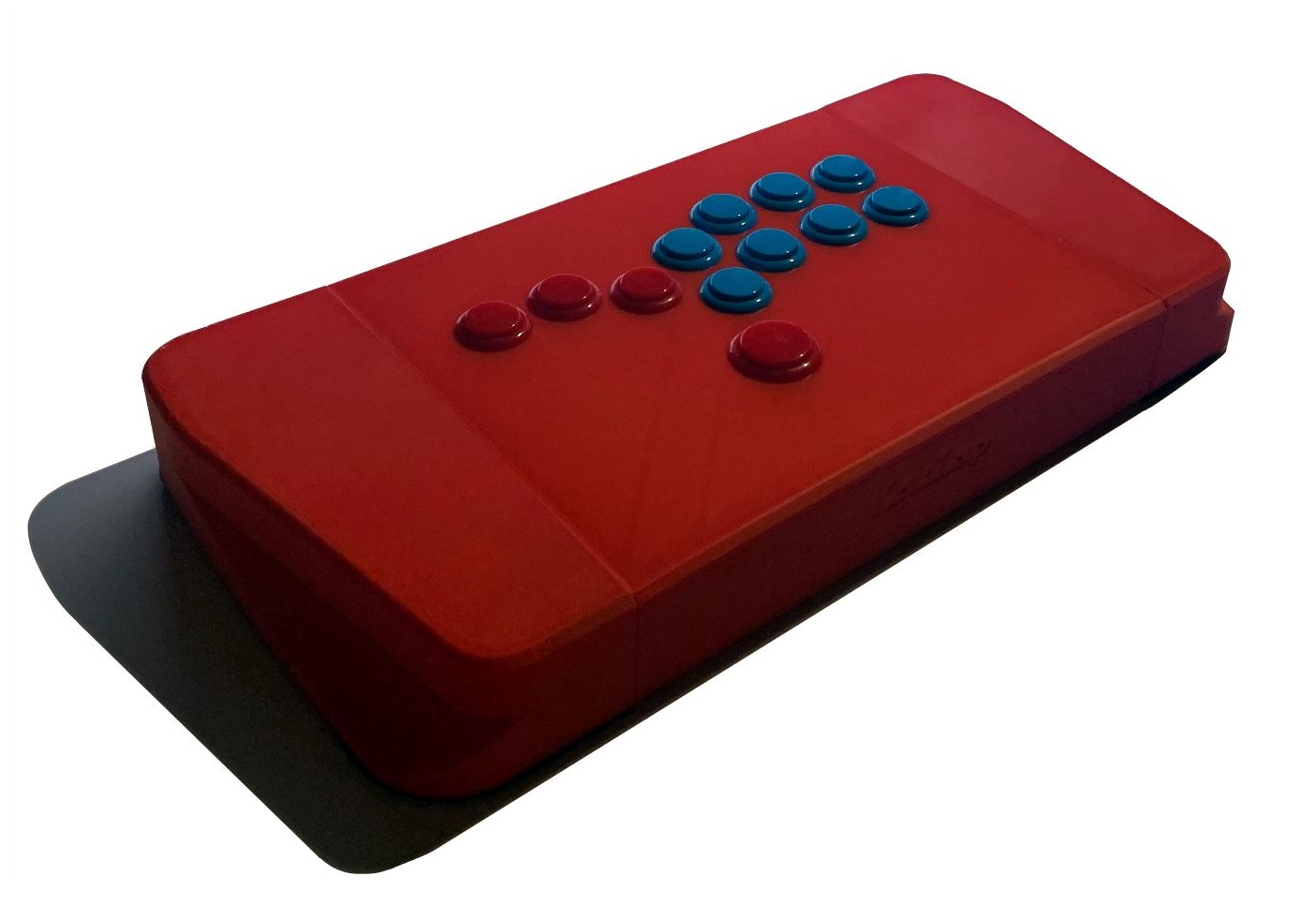
Hitbox - Arcade Stick
prusaprinters
<p>This is a 3d-printed hitbox case I've made for myself some time ago. I have wanted to upload it to the site, but have postponed it several times due to the complexity and amount of work required to make it upload worthy.</p><p>So who is this case for? </p><p>If you are like me and have made custom arcade sticks before and have an understanding of the process, or if you have some unused arcade stick buttons and PCB's laying around, this is for you.</p><p> </p><p><strong>Dimensions and interfaces:</strong></p><figure class="image image_resized" style="width:75%;"><img src="https://media.prusaprinters.org/media/prints/118150/rich_content/1638b312-4162-4f2b-8cc3-bff955ceae18/dims.png#%7B%22uuid%22%3A%2299c9d136-6342-4204-b275-54d4ca7dfdae%22%2C%22w%22%3A1091%2C%22h%22%3A819%7D"></figure><figure class="image image_resized" style="width:75%;"><img src="https://media.prusaprinters.org/media/prints/118150/rich_content/7286ccfd-06a4-419a-9f16-b8992f5c654f/internal.png#%7B%22uuid%22%3A%223df22362-f9ff-4486-b93a-726f601b366d%22%2C%22w%22%3A751%2C%22h%22%3A286%7D"></figure><figure class="image image_resized" style="width:75%;"><img src="https://media.prusaprinters.org/media/prints/118150/rich_content/da78d3f6-e3ce-4e50-8dbe-809dd6780e27/pcb-spacing.png#%7B%22uuid%22%3A%22ec77a30f-63fa-4685-8112-f7c93f2e93bc%22%2C%22w%22%3A699%2C%22h%22%3A597%7D"></figure><p> </p><p><strong>3d Printed Parts:</strong></p><figure class="image"><img src="https://media.prusaprinters.org/media/prints/118150/rich_content/190f2a28-b72d-40fc-abb4-6e197f0fec16/printed-parts.png#%7B%22uuid%22%3A%22d0ea66e7-3ae2-4c50-af77-26c4e9da04d2%22%2C%22w%22%3A1315%2C%22h%22%3A854%7D"></figure><p><strong>---------------------------------------------------------------------------------------------------------</strong></p><p><strong>Hardware:</strong></p><p>This is what I have used, different PCB can be used as long as it fits. Also note that connectors on cables/wiring needs to bent 90 degrees in order to fit inside the case (explained below).</p><p> </p><p>- Brook Zero Pi Fighting Board <a href="https://www.amazon.com/dp/B09637ZPSF/ref=emc_b_5_i">https://www.amazon.com/dp/B09637ZPSF/ref=emc_b_5_i</a> </p><p> (I know for a fact that PS360+ does also fit)</p><p>1x Neutrik NAUSB-W-B Reversible USB Genderchanger <a href="https://www.amazon.com/Neutrik-NAUSB-W-B-Reversible-Genderchanger-D-Housing/dp/B003VSXQVI/ref=sr_1_3?crid=1IIRPWEX1DH2P&">https://www.amazon.com/Neutrik-NAUSB-W-B-Reversible-Genderchanger-D-Housing/dp/B003VSXQVI/ref=sr_1_3?crid=1IIRPWEX1DH2P&</a></p><p>- Fasteners for Neutrik connector (2x M3x15 countersunk screw , 2x M3 Nut)</p><p>14x Sanwa OBSN-24 Arcade buttons (the version with screw)<br> </p><p>1x Sanwa OBSN-30 Arcade Buttons (the version with screw)<br> </p><p>- Wiring for buttons<br> </p><p>1 x USB Cable (from neutrik connector to console/PC)</p><p> </p><p>1x USB cable (from PCB to neutrik connector)<br> </p><p>8x M4x10mm Countersunk screw<br> </p><p>4x M4x15mm Button Head screw<br> </p><p>8x M6x20mm Button Head Screw</p><p> </p><p>8x M6x12x7 Heat Insert Nut <a href="https://www.amazon.com/dp/B08Z7541M5?ref=ppx_yo2_dt_b_product_details&th=1">https://www.amazon.com/dp/B08Z7541M5?ref=ppx_yo2_dt_b_product_details&th=1</a></p><p> </p><p>12x M4x6x6 Heat Insert Nut <a href="https://www.amazon.com/dp/B08Z84DGZ8?psc=1&ref=ppx_yo2_dt_b_product_details">https://www.amazon.com/dp/B08Z84DGZ8?psc=1&ref=ppx_yo2_dt_b_product_details</a></p><p> </p><p><strong>---------------------------------------------------------------------------------------------------------</strong></p><p><strong>Print Instructions:</strong></p><figure class="image"><img src="https://media.prusaprinters.org/media/prints/118150/rich_content/43f6faff-b8cc-4774-a2b0-64b388eca4ec/print-orientation.png#%7B%22uuid%22%3A%229d469e30-d6d0-4732-854b-9cd9208f54d1%22%2C%22w%22%3A1459%2C%22h%22%3A903%7D"></figure><p>The parts are designed to be printed in the orientation as shown above. Left and Right bodies require support. Main body, Bottom Panel, and TPU Feet does not require any support.</p><p><strong>Print Settings I've used:</strong></p><p><i>MAIN, RIGHT AND LEFT BODIES:</i></p><p>Material: PLA/PETG</p><p>Infill: minimum 10% - Gyroid</p><p>Layer height: 0.3 mm</p><p>Perimeters: 3</p><p>Brim: Yes</p><p>Support: yes on “right” and “left body"</p><p> </p><p>Support material is required as shown below, this can be achieved by using the “paint on supports” function in prusaslicer. This is the <strong>ONLY</strong> place that needs support material in the project. </p><p> </p><figure class="image image_resized" style="width:75%;"><img src="https://media.prusaprinters.org/media/prints/118150/rich_content/41a802b2-9592-4807-ba93-2ce63cf8a72d/image.png#%7B%22uuid%22%3A%22df8d048f-c673-4c1b-b16d-1dacddea3a8b%22%2C%22w%22%3A1345%2C%22h%22%3A975%7D"></figure><p> </p><p><i>BOTTOM PANEL:</i></p><p>Material: PLA or Petg</p><p>Infill: 20%</p><p>Layer height: 0.3 mm</p><p>Perimeters: 3</p><p> </p><p><i>TPU FEET:</i></p><p>Material: TPU</p><p>Infill: 15%</p><p>Layer height: 0.2 mm</p><p>Perimeters: 3</p><p><strong>---------------------------------------------------------------------------------------------------------</strong></p><p> </p><p><strong>Assembly Instructions</strong></p><p>1. Bodies</p><p><img src="https://media.prusaprinters.org/media/prints/118150/rich_content/25b77dbf-3c8f-45ef-ae60-e5dab9d546bf/1.png#%7B%22uuid%22%3A%22304f47cc-3523-4309-82b7-9b56e684a350%22%2C%22w%22%3A1583%2C%22h%22%3A1026%7D"><br> </p><p> </p><p>2. Install 4x “M6 Heat Insert Nut” to “Left Body”</p><figure class="image image_resized" style="width:75%;"><img src="https://media.prusaprinters.org/media/prints/118150/rich_content/02bc5937-7a11-4de2-82da-6e0e1060a84c/2.png#%7B%22uuid%22%3A%22fe1d6a73-47b3-45eb-ba5d-92e31ff08410%22%2C%22w%22%3A857%2C%22h%22%3A675%7D"></figure><p> </p><p>2.1 Make sure the heat inserts are as square as possible, as shown below. Run a quick test by screwing in M6 screws, adjust by reheating if necessary.</p><p> </p><figure class="image image_resized" style="width:75%;"><img src="https://media.prusaprinters.org/media/prints/118150/rich_content/1b85bbe6-7eaf-41ca-9332-b7a60f5c04bb/square-bolts.png#%7B%22uuid%22%3A%224eb1a554-2c15-46e5-b871-bca204d04e64%22%2C%22w%22%3A1060%2C%22h%22%3A608%7D"></figure><p> </p><p>3. Install 2x “M4 Heat Insert Nut”</p><figure class="image image_resized" style="width:75%;"><img src="https://media.prusaprinters.org/media/prints/118150/rich_content/7c318bda-9c7e-4763-935f-49464513809c/3.png#%7B%22uuid%22%3A%225d12f0cd-eed3-4233-87f4-b93aae8af5f2%22%2C%22w%22%3A849%2C%22h%22%3A678%7D"></figure><figure class="image image_resized" style="width:75%;"><img src="https://media.prusaprinters.org/media/prints/118150/rich_content/38bf4a98-3d9b-45ad-9f7d-9d033325bc65/4.png#%7B%22uuid%22%3A%2272d45f66-8a00-4ebb-b69a-1dedbc8db69c%22%2C%22w%22%3A852%2C%22h%22%3A677%7D"></figure><p>4. Repeat steps 2 and 3 on “Right Body”</p><p> </p><p>5. Install 8x “M4 Heat Insert Nut” on “Main Body”</p><figure class="image image_resized" style="width:75%;"><img src="https://media.prusaprinters.org/media/prints/118150/rich_content/52e44998-9ed8-4025-9007-9f622ce4b167/5.png#%7B%22uuid%22%3A%22a65e3033-1001-49d3-9233-6cf04811c828%22%2C%22w%22%3A1135%2C%22h%22%3A807%7D"></figure><figure class="image image_resized" style="width:75%;"><img src="https://media.prusaprinters.org/media/prints/118150/rich_content/5d733ef7-76fa-4b0f-b087-236bd04699c2/6.png#%7B%22uuid%22%3A%22f4ecac61-f42e-45ac-a635-e85c22db4d2f%22%2C%22w%22%3A1132%2C%22h%22%3A791%7D"></figure><p> </p><p>6. Assemble “Left Body” and “Right body” to “Main body” with 8x ”M6x20mm Button Head Screw”</p><figure class="image image_resized" style="width:75%;"><img src="https://media.prusaprinters.org/media/prints/118150/rich_content/c5cc161d-af72-4528-b4fa-c0b1962bff04/7.png#%7B%22uuid%22%3A%22b50580ba-88cc-4ccf-9ff8-9252929d23e6%22%2C%22w%22%3A1318%2C%22h%22%3A860%7D"></figure><p>7. Install arcade buttons</p><figure class="image image_resized" style="width:75%;"><img src="https://media.prusaprinters.org/media/prints/118150/rich_content/692cc523-5acd-4642-bdf3-0523cf0f0b5a/8.png#%7B%22uuid%22%3A%2212d4a3f3-b60c-4000-b4cc-de0bcbfdde19%22%2C%22w%22%3A1315%2C%22h%22%3A868%7D"></figure><p> </p><p>8. Install Neutrik connector</p><figure class="image image_resized" style="width:75%;"><img src="https://media.prusaprinters.org/media/prints/118150/rich_content/f959faaf-f4e9-4c22-a244-9af4cdc40e71/9.png#%7B%22uuid%22%3A%22d53a9241-54ee-44d6-a936-cd2822aa03a8%22%2C%22w%22%3A1321%2C%22h%22%3A865%7D"></figure><p> </p><p>9. Install PCB and wiring. Please note that you need 4x M3x10mm self tapping screws to install the PCB to the case.</p><figure class="image image_resized" style="width:75%;"><img src="https://media.prusaprinters.org/media/prints/118150/rich_content/6ca0c015-4da6-45bd-b6b7-8fd2a2a97a00/pcb.jpg#%7B%22uuid%22%3A%22eb150607-0718-4fe0-bed4-4871951dde6e%22%2C%22w%22%3A737%2C%22h%22%3A529%7D"></figure><figure class="image image_resized" style="width:75%;"><img src="https://media.prusaprinters.org/media/prints/118150/rich_content/4ecad584-bdf6-4574-9e7b-54039e5625b7/15.png#%7B%22uuid%22%3A%22367a31b1-ba79-4e4f-8884-625e7fe999a2%22%2C%22w%22%3A1383%2C%22h%22%3A787%7D"></figure><p> </p><p>Please note that connectors on the button cables needs to be bent 90 degrees in order to fit inside the case, see picture below.</p><figure class="image image_resized" style="width:75%;"><img src="https://media.prusaprinters.org/media/prints/118150/rich_content/cf0d33ad-eeb1-4b35-96c4-e45e15a80fdc/cables.jpg#%7B%22uuid%22%3A%222e2d51fd-f983-4848-8048-10a463513490%22%2C%22w%22%3A2224%2C%22h%22%3A1368%7D"></figure><p> </p><p> </p><p>10. Install “Bottom Panel” with 8x “M4x10mm Countersunk screw”</p><figure class="image image_resized" style="width:75%;"><img src="https://media.prusaprinters.org/media/prints/118150/rich_content/4998c5e6-819a-430c-a106-17a4cc37503d/11.png#%7B%22uuid%22%3A%22927d6a71-c3f0-4628-9f2c-7ef2c5da9158%22%2C%22w%22%3A1345%2C%22h%22%3A882%7D"></figure><p> </p><p>11. </p><p><strong>Option 1)</strong></p><p><strong> </strong>Install 4x “TPU feet” with 4x “M4x15mm Button Head Screw”</p><figure class="image image_resized" style="width:75%;"><img src="https://media.prusaprinters.org/media/prints/118150/rich_content/2d9c5932-f20e-4c81-a2a8-fb2a5326de04/12.png#%7B%22uuid%22%3A%223f7da57b-a25b-4acc-9f8b-6517c8240504%22%2C%22w%22%3A1335%2C%22h%22%3A878%7D"></figure><p><strong>Option 2)</strong></p><p>Cut a large mouse pad to the shape of the arcade stick and tape it to the arcade stick with double sided tape. This is the option I use.</p><figure class="image image_resized" style="width:75%;"><img src="https://media.prusaprinters.org/media/prints/118150/rich_content/269aa5e5-0537-4bba-9f4c-7e34ab32fe3a/14.png#%7B%22uuid%22%3A%2275ae06ea-85ea-4ed6-8f79-6b05905fc6f3%22%2C%22w%22%3A1312%2C%22h%22%3A865%7D"></figure><p> </p><p>12. Assembly is done!</p><figure class="image image_resized" style="width:75%;"><img src="https://media.prusaprinters.org/media/prints/118150/rich_content/f0d674cb-99ed-40ce-b6f6-d3fb6b67b1ee/13.png#%7B%22uuid%22%3A%220d8174dc-4858-4ded-a16a-0f240d644ecf%22%2C%22w%22%3A1349%2C%22h%22%3A877%7D"></figure><p> </p>
With this file you will be able to print Hitbox - Arcade Stick with your 3D printer. Click on the button and save the file on your computer to work, edit or customize your design. You can also find more 3D designs for printers on Hitbox - Arcade Stick.
