HevORT XHD12 Gantry/Carriage
prusaprinters
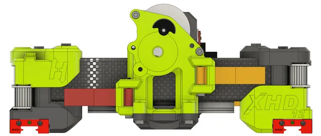
Welcome to the HevORT XHD12! What is it?Several members of the HevORT community were starting to build 3d printers larger than 500mm which is about the maximum that the standard 20mm gantry beams can handle before having rigidity issues that prevent them from using the high speeds that a HevORT is capable of…enter the XHD12 gantry.The XHD12 (Xtra Heavy Duty 12) is essentially the HD12-CFx gantry/carriage that has been stretched to fit a 30mm carbon fiber square tube and maintain the use of the HextrudORT extruder system. All standard clearances and alignments have been preserved so that this will function seamlessly with the other HD12 components (pulley & motor mounts). Other FeaturesMatching design contours to provide maximum movement on the X-axis. At least 30mm gained over the original HD12-CFx in the X-axisPermanent ADXL345 mountCable strain relief mount with integrated screw clampOptical end stop relocated to the right rear side with integrated mount (original mounting position is front left)Compatible with the HextrudORT system that has multiple hotend options available.MGN12H and MGN9H compatible carriages are available. Additional ConsiderationsI have not created any cooling fan, hotend supports, or leveling probe mounts. I am under the assumption that if you are building a larger HevORT that you have the ability to make these to suit your application. Potential updates will be made in the future to adapt the E3D Revo system as they release more complete offerings. The carriage bottom has intentionally been left flat and large to facilitate easy modifying of this design for your needs.Each Y linear rail carriage screw is designed to have between 2-3mm of thread engagement. The holes that they each go into are different depths, pre-install them and it will be obvious if you have the right screw in the right hole or not. !!!Caution!!! - The Gap around the CF tube is only .5mm per side which means no screws can protrude beyond their designated holes. Trim to length accordingly!!! Screw Count Totals(2) M2.5x10mm Button head screws(2) M2.5 nuts(9)M3x6mm Socket cap screws(2)M3x10 Socket cap screws(2)M3x12 Socket cap screws(4)M3x20 Socket cap screws(3)M3x22.5 Socket cap screws(1)M3x25 Socket cap screws(2)M3x30 Socket cap screws(10)M3 Nuts(4) M4x45mm Socket Cap Screws(4) M4 nuts(4) Carbon Fiber Rod 5mmx30mm(1) Carbon Fiber Rod 5mmx 50mmMGN9H: (4) M3x12mm CountersinkMGN12H: (4) M3x8mm CountersinkScrew Count Per PartLeft Gantry Upper(2 )M4x45 Socket(1) 30mm CF Rod (Lower Pulley)Left Gantry Lower(4) M3x6(2) M3x20(2) M3 nut(2) M4 nut(1) 30mm CF Rod (Upper Pulley) Right Gantry Upper(2 )M4x45 Socket(1) 30mm CF Rod (Lower Pulley)Right Gantry Lower(4) M3x6(1) M3x20(1) M3x22.5(2) M3 nut(2) M4 nut(1) 30mm CF Rod (Upper Pulley) Carriage Front Plate(1) M3x6 (upper motor)(2) M3x12 (front lower)(2) M3x22.5 (right belt, right carriage)(1) M3x25 (left belt )(2) M3x30 (left hextrudort, left carriage)(3) M3 nutsCarriage Body(2) M2.5x10mm buttonhead (ADXL)(2) M2.5 nuts (optional)(2)M3x10 (end stop)(1) M3x20 (strain relief)(3) M3 nutMGN9H: (4) M3x12mm CountersinkMGN12H: (4) M3x8mm Countersink Print Setting SuggestionsThese parts are optimized for .2mm layer heights, .25mm will also work if greater strength is needed.These parts are optimized for .6mm extrusion width for strength. Extruding thicker line widths may cause aesthetic imperfections due to internal clearances of cavities for screws & pins. .4mm extrusion width will also be suitable if you are not familiar with altering extrusion width.Material: ESUN ABS+ has a low layer adhesion for support material so this often creates the cleanest support removal. Highly recommended for strength and temperature resistance. __________________________________________________________________________________________________________________Extra background for fun:I started this project in early march '22 after being asked about potentially building a larger format printer. I started to make these parts as a simple exploration to see if it was possible to stretch the components or if the features would be too complex to split. It worked and I didn't end up building a printer but continued to make this modification for the community.As a designer I wanted to really focus on making these parts look like they fit into the original design aesthetic while still having a slightly more flashy appearance to it. A style that I really developed was allowing the internal features and components show on the outer surfaces to create a strong mechanical narrative. The original HevORT builds also use off-angle faces to create strong corners and very robust shapes. I tried to carry through the use of strong angles and softer lines but in a way that bring out that impression of robust strength.The carriage was the the most complex of the parts to stretch and has over 100 sketches that define the features and constraints! Each of the gantry parts have about 30-50 sketches to bring the features to life. Combined, this project probably has about 250 hours or so baked into it? Extremely gratifying now that it is finished and came out as well as I think it did. I hope you will be able to enjoy using it as much as I did creating it!Happy Large Format Printing!
With this file you will be able to print HevORT XHD12 Gantry/Carriage with your 3D printer. Click on the button and save the file on your computer to work, edit or customize your design. You can also find more 3D designs for printers on HevORT XHD12 Gantry/Carriage.