Greg's B'Wadestruder / geared B'struder (bowden-feed extruder), v3
prusaprinters
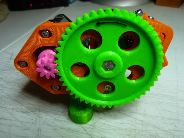
This project is an elegant geared-drive, bowden feed extruder, based on tempo502's B'struder.It combines the idler arm from there for PC4-M6 pneumatic/bowden fittings, with your basic Wade gears.With a suitably-modified idler arm, it should be possible to use 2.85/3 mm filament, if your stock thereof is all from the dark ages. ;-)The B'struder "plate" has been heavily modified to remove all of the former mounting holes, the thickness has been adjusted slightly, space has been added for a bearing where the motor axle hole used to be, one edge has been extended out and thickened to hold the motor off to the side, large holes have been added to reduce its mass a bit, a small hole was added to the spring's back stop so that a screw can be driven in to tension the spring, and a few other holes and nut traps have been added to the upright part to allow the top plate to attach to it.The Wade gears are based on ronanwarrior's high-resolution Greg's Wade Reloaded extruder gears, but greatly modified. Like his, these have a ratio of 47:9 (5.222:1).You can either print and use the idler arm included here, or grab one of tempo502's other variants from his Thingiverse project.With the pictured motor (just a common ~40 mm NEMA17 stepper), this extruder can push filament at 150 mm/sec reliably during retractions.Vitamins:2, 625ZZ bearings.3, 623ZZ bearings.1, M4 x 4-6 mm screw, Allen, square, plain Torx, or something vaguely like these. Cap-head preferred.1, M5 x 40 mm hex bolt.1, M5 nylock nut, or two regular M5 nuts if you can get thin ones.2, M4 or M5 x 16 screws for the 2020 mount, if you use it, plus two M3 x 20 screws if you're using the noise-reducing version.• 2, washers to fit the M5 bolt, preferably with an outer diameter on the small side.• A "wood" or "sheet metal" screw of some kind, 3 to 3.5 mm in diameter, 15 to 20 mm length. Something self-drilling would be best, but isn't critical.• A suitable idler arm spring, 20 to 25 mm length.• Assorted M3 screws, nuts, and washers to put it all together. Lengths range from 8 to 45 mm. Optionally, one 40-50 mm long M4 screw to replace the longest M3 screw (then you can omit its nut and washer)• A PC4-M6 pneumatic/bowden fitting, whatever fits the idler arm you're using. I recommend the kind that are bored all the way through (i.e. so that the bowden tube can pass completely through it), as these hold the tube better.• A suitable drive gear. It doesn't matter TOO much what kind you choose, as long as it works. :-) There are four basic classes of these, and I mention this here because it'll be important later:some have a knurled surface such as those meant for Ultimaker printerssome have a simple, straight tooth profile that looks like it could have been extruded through a die, such as those 26, 28, 32, and 40 tooth brass or steel gears you find on eBay.some gears are a plain, smooth cylinder with a "working" area near one end, consisting of either a strip of teeth molded into the gear, or of a machined groove that looks like it was cut with a thread tap, such as genuine MK7, MK8, MK10, Hobb-Goblin, etc.some look like they started out as a simple, flat tooth profile that's then had a continuous groove machined into the teeth near one end, to create the hobbed working area (they're sometimes sold as "MK8", even though they're not even close).Although the phrase "hobbed gear" is often used to describe just about any kind of 3d printer drive gear, regardless of the shape or profile of its teeth, for simplicity, I'll use that term to refer only to these latter two classes (whether the teeth are cast or machined).Assembly:Print everything and clear out the support bridges in the base plate and top plate.Start building the drive assembly:File or grind a flat spot into the M5 bolt in the area where your drive gear's grub screw will grip on. It need not be particularly deep, maybe 1 mm, as long as it's deep enough that the drive gear's grub screw won't stick out too far. Make the surface as flat as possible, or it can be slightly concave if that's easier (i.e. if you use a rotary tool to do the job). Exactly where you put this flat depends on the specific drive gear you'll be using and how you orient it. Don't make the flat so long that it reaches into either bearing.Add a bit of super glue or cement to the flats of the bolt head, and push it through the gear, seating it fully.Add a washer and M5 nutTorque the nut down, while making sure to keep the bolt square to the gear. Check it from multiple angles, spin it, etc. It MUST be square and true.Set the drive assembly aside. Unless you live in a rain forest or you do your assembly work inside a sauna, the glue probably needs a few minutes to cure anyway. ;-)Assemble the idler arm:Use a 2 mm drill bit to clear out the filament path, and use your hobby knife to clean up the area in the middle of the curved side.Trim the two holes at the "shoulder" end of the idler arm and press-in two 623ZZ bearings. Note: the one that'll face away from the base plate seats in deeper than the other one.Insert a third 623ZZ bearing into the recess in the middle of the idler arm.Put an M3 washer on each side of that bearing, if possible.Insert an M3 nut into the trap next to the bearing.From the side of the arm that faces away from the base plate, thread a 12 to 14 mm M3 screw into that nut and tighten it down. Don't over-tighten.Carefully line up the threads and install the PC4-M6 fitting into the end. After installing it, rotate it a little so that one of the flats lines up parallel with the side of the arm (so that it won't scrape against the base plate).Press two M3 nuts into the two recesses on the inside faces of the vertical part of the base plate (the idler arm back stop as I call it). You may have to use your soldering iron to heat-set them.Insert an M3 nylock nut into the trap on the underside of the base plate. You'll probably need to super glue it into place.Optional (recommended): put the nut in upside down, so that the rounded, locking side is in the recess, so that the screw you'll use to mount the idler arm will hit the locking side first, allowing for a shorter screw.Using a 20 mm M3 screw with a washer under the head, install the idler arm into the base plate, with the curved side facing away from the upright part of the base plate (duh :-) ). Tighten it down securely, until it presses the idler arm's bearing in all the way, then back off about 1/8 turn, just until the idler arm can pivot freely.Insert your idler tension spring through the large hole in the base plate's back stop section, seating into the idler arm. Add a short M4 Allen-head to the end of the spring. Since there's nothing in place yet to block the idler arm from swinging out too far, the spring and screw may fall out unless you keep the idler arm pressed against the back stop. It may help to temporarily tighten the idler arm's shoulder screw a bit "too much", to make it hold the arm steady, and then back it off later, when appropriate.Using two 9 mm M3 screws in the two holes with the countersink flats, install the top plate onto the base plate, taking care not to let the spring and its screw fall out.Push a 45 to 50 mm M3 screw with washer into the diagonally-oriented hole running through the bottom-most parts of the top plate and base plate. Secure the other end with a washer and nut. Alternatively, you may simply drive an M4 x 40 mm screw into and all the way through the diagonal hole and not bother with washers and nut. It'll keep itself in place by friction as long as you don't over-tighten it.Finish the drive assembly and install it:Remove the M5 nut from the bolt, but keep it handy, you may need it later. Leave the washer in place (it'll probably be stuck-on by the super glue anyway).Add a 625ZZ bearing.Add your drive gear. If you're using the hobbed kind, put the "working" end in first.Thread the drive gear's grub screw in just enough to align it with the flat on the M5 bolt, but not enough to prevent the gear moving up and down freely.Insert the drive assembly into the base plate, pressing the drive assembly's bearing fully into its recess.Press a 625ZZ bearing into the top plate, engaging the end of the bolt.If you're using a gear with a knurled surface or a simple flat tooth profile, adjust its position to make sure its teeth cross the filament path and re-torque the grub screw, then skip ahead to step 12.If you're using a hobbed gear:a. Use a piece of filament to help align the gear's working part to the idler arm's filament pathb. Once it's aligned, rotate the gear to align its grub screw with the flat on the drive bolt, and torque the screw down.Add a washer and nylock nut to the end of the bolt, and tighten it until it begins to pull the two 625ZZ bearings together. The top plate is braced to prevent it bending, so DO NOT tighten the nut so much that it damages the bearing.If you're using a hobbed gear, re-check the filament path alignment by looking through either end of the idler arm (so that you can see how the hobbed area's curve aligns with the filament path hole). It is critical that the hobbed area be as centered on the filament path as possible, otherwise the filament may try to "walk" up out of the hobbed area during some extruder moves, leading to inconsistent flow or bad retractions.Pull back on the idler arm to relieve pressure on the drive assembly, and double-check that the drive assembly turns freely, looks square enough to do its job, and doesn't have excessive play (especially end to end). You will likely need to alternate a few times between pulling-back the idler arm and adjusting the M5 nut.Drive in a 15 to 20 mm sheet metal or wood screw into the hole opposite the tension spring. Something 3 to 3.5 mm diameter, with sharp threads that can bite the plastic nicely. Make sure the tip of the screw engages the Allen socket in the screw in the end of the spring.You'll use this screw to set the spring tension when you're ready to start using the extruder.Press an M3 nut into the trap in the bottom of the small gear.Thread an 8 to 9 mm M3 screw into the side hole and part-way into that nut.Place the small gear onto the motor shaft, round end first, and thread that screw in just enough to align the gear with the flat on the motor's shaft.Insert four M3 screws (with washers if possible) into the base plate and use them to hold the motor in place, but do not tighten them. Take care to orient the motor's connector/wires correctly for your setup. If you intend to use the 2020 mounting bracket, insert it between the motor and the base plate. Depending on the depth of the screw holes in your motor and whether you're using that bracket, the screw length will vary, in the 10 to 17 mm range.Rotate the printed gears so that the small gear's set screw is exposed to the access hole on the side of the base plate.Adjust the height of the small gear, aligning it precisely with the large gear (I used the centerline of the gears' herringbone pattern as my guide), making sure that the large gear remains parallel to the base plate, and tighten down the small gear's screw, making sure to keep it aligned to the flat on the shaft. Don't over-tighten it.Press the motor toward the large gear, to take up as much gear lash/slack as possible (but don't cram them together too hard), and tighten its mounting screws while holding the motor in place, starting with the screw furthest from the large gear, then the one under the large gear, then the other two. Doing them in this order ensures that the motor will tend to lean slightly away from the large gear as it's tightened down, before it squares-up, helping prevent the gears being crammed together too hard.Pull back on the idler and check again that everything turns freely and smoothly.Apply a small amount of oil to the two 625ZZ bearings and to the Wade gears' teeth. Be careful not to get any oil onto the drive gear or anything else that'll get into the filament path.Optional: if you used the kind of PC4-M6 fitting which the tube can pass all the way through, you may want to loosen it a little, push the tube all the way in as far as it'll go, then tighten the fitting down, thus pressing the end of the tube against the base of the threaded hole. This will reduce, perhaps even eliminate the tendency for the tube to waggle back and forth during retractions. Just don't loosen the fitting so much that it crushes the end of the tube when it's re-tightened (a quarter turn is plenty). You should also put a clip under the fitting's black/blue cap to keep it pressed out.The whole assembly can then be mounted to your machine by taking two of the screws out of the back of the motor and replacing them with longer ones, or by using the 2020 mounting bracket and M4 or M5 screws and suitable T-nuts.The bracket should be useful for mounting onto other things besides 2020 extrusion.There are two versions of the 2020 mount: a one-piece design that's just, well, a bracket, and a two piece noise-reducing design. In that one, print the "B" piece in TPU and fasten it to your frame, then print "A" piece in PETG or whatever, build it into the extruder, and fasten it to the "A" piece.This extruder was inspired by ask0045's geared B'struder (http://www.thingiverse.com/thing:1694683) and follows a somewhat similar design.Changelog2022-04-14: I was having trouble with TPU popping out of the arm because there was too much clearance around the hobbed gear. I've tweaked the positioning and size of the clearance cutout and the positioning of the idler bearing, to fix that and improve the filament alignment as well. Also, I've altered the top plate model to make it easier to reach the hobbed gear for cleaning or whatever.2021-02-17: Added "MK8" and "11 mm" markings to the two idler arms.2021-01-19: I reworked the design a bit, making the following changes:Re-modeled the idler arm into a much higher resolution (i.e. smoother curves).Created a version of the idler arm for 11 mm plain drive gears, which should provide better guarding around the filament path, as I was having problems printing TPU with the standard idler arm and that kind of gear (it kept bunching up on the output side of the gear)Added a brace to the motor-facing end of the top plate, so that the drive assembly's bolt and nut can't pull the top plate inward anymore. This also eliminates the need to use a bunch of washers on either side of the drive gear for alignment.Enlarged the hole in the center of the top plate's bearing race to eliminate contact with the bearing' hub.Pushed the idler spring pit in the base plate all the way though the plate, making it into a hole, and moved the screw hole itself (that is, the small one that the screw bites into) over to the top plate, which taken together lowers the minimum spring pressure -- good for big hobbed gears.Added an arrow to the big gear to indicate the extrusion direction, just because I could. :-)2020-09-01: Gave the front surface of the big gear an inset surface and filleted edges similar to what it had before I made it thinner, just to give it some style. Also slightly thickened the surface around the hole that the underside of the bolt head sits on.2020-08-16: Reworked the two gears again. On the small one, I moved the nut trap center-ward a bit more to increase the amount of material between the nut and the screw head, for added strength, and slid the screw bore forward a bit so that it'll be center in the base plate's access hole. The nut trap overlaps the center bore but that's okay, it's still far enough outward to not be an issue. Also, I didn't like how the round part wasn't perfectly measured and centered (too many changes over time without being careful enough, I suppose). Fixed. On the large gear, there was some distorted geometry that I didn't catch until just now. That's fixed as well. Probably had no effect on the use of the part, but better safe than sorry.2020-08-15.4: Noticed the base plate had some non-mainfold vertexes. Fixed.2020-08-15.3: Made that hole a bit larger, and added a support bridge over it.2020-08-15.2: Added a large hole into the base plate's bearing recess so that one can insert/remove the drive assembly from one side, without removing the top plate.2020-08-15: Reworked the two Wade gears to reduce their mass, and altered the top plate to put the 625ZZ bearing on the outside so that it along with the one in the base plate will properly hold the drive assembly in alignment without the need for washers. The gear ratio remains unchanged.2020-04-11: Added noise-reducing version of the 2020 mounting bracket. It rotates the extruder by 90° as well, putting the motor and drive axles parallel to the 2020 it's mounted on (I originally designed it for my Hypercube).2020-01-11: Rotated the motor by 45° so that all four screws are accessible without removing the large gear (one via the holes in the gear). Reworked the 2020 bracket accordingly, so that the extruder keeps the same overall orientation.2020-01-10.2: Re-linked standard library to account for recent changes.2020-01-10: Added bridging over the 2020 bracket's two mounting holes, and made them bigger, to actually fit M5 screws. Sorry for the errors, folks. It's only just recently I've found myself needing to actually USE this extruder again, to say nothing of needing the 2020 bracket. :-)2020-01-09: Added bridging over some of the baseplate's holes, and tapered the studs on the top plate's diagonal screw, eliminating the need for supports.2020-01-06: Exchanged the motor mount screw holes for slots, so that you can move the motor as needed to set the gear lash and compensate for wear. I also added insets around the 2020 bracket's two M5 mount holes, so that you can use 16 mm screws to fasten it to the 2020.2019-12-08: No functional changes this time around... I just replaced the 2020 in the .blend with my own model (created from Misumi's Series-5 technical drawing), swapped the motor model for an updated, more-detailed version I created from it, which I use in other projects, and replaced all the screws, nuts, etc. with better ones, for the sake of appearance in the .blend (and the render).2018-03-13: Many parts were not properly rotated and aligned for printing (although most slicers can easily correct this). Fixed. Also corrected the length of the M5 bolt in the .blend (and all-parts .stl). If you've already printed this since 2016-10-22, you don't need to do anything.2016-10-22: Somehow the motor's screw holes got lost from the revised 2020 bracket. Fixed.2016-10-21.6: Replaced the bracket with a much shorter version that should keep everything out of way of anything attached to the 2020 extrusion.2016-10-21.5: Fixed the bracket. I forgot to add a hole for the small gear to pass through. Derp. :-)2016-10-21.4: Replaced the mounting bracket with an "L" version that should be more useful.2016-10-21.3: Added a mounting bracket to fit 2020 extrusion. Holes are sized for M4 screws.2016-10-21.2: Noticed and fixed an error in the base plate (a vertex got moved for some reason, screwing up the top of the baseplate where the motor goes).2016-10-21.1: New .blend with all the screws, bearings, and other hardware included, a few existing bits simplified (well, sorta), and redundant stuff removed. The actual printable parts are unchanged. Added an exploded view diagram, should help with assembly.2016-10-20: Replaced all files with version 2. The first version had a problem with the M5 nylock nut working loose enough to allow the bolt and large gear to lean sideways, making the extruder noisy and somewhat inaccurate during retracts. Now the end of the bolt is held steady by an upper plate screwed onto the base plate, into which one of the two 625ZZ bearings has been moved. The base plate has been modified to add the necessary holes and nut traps for those screws. This new version is MUCH quieter since the gears now stay well-aligned, and it can reliably turn about 10 percent faster, as well. The printed gears themselves are unchanged from v1.Print instructionsNotesPrint everything at a somewhat high infill density - 40-50% ought to do.How I Designed ThisI started by loading the B'struder plate, and removing all of the holes, save for the central one and the small one that holds the idler arm. I then un-triangulated the whole thing to make it easier to work on, created pockets for the two bearings, and so on.I then added an extension for the motor, with the two aligned to place a 0.15mm gap between the two sets of gear teeth.Finally, I created the top plate starting from an ordinary cube, with lots of edge subdivision and beveling to create the "L" shape and rounded corners.All work done in Blender.The Blender work file depends on my standard parts/materials library, which can be found here: https://www.prusaprinters.org/prints/16640-my-blender-3d-printing-partsmaterials-library ... If you get errors regarding missing objects/materials, download that file and do whatever you need to to get Blender to pick it up.The two bearings depicted in the .blend are from my 7½-shot-pellet-based 625ZZ model (https://www.prusaprinters.org/prints/7455-625-625zz-bearing-using-7-12-shot).
With this file you will be able to print Greg's B'Wadestruder / geared B'struder (bowden-feed extruder), v3 with your 3D printer. Click on the button and save the file on your computer to work, edit or customize your design. You can also find more 3D designs for printers on Greg's B'Wadestruder / geared B'struder (bowden-feed extruder), v3.