Gravity Feeder for Lack Enclosure
prusaprinters
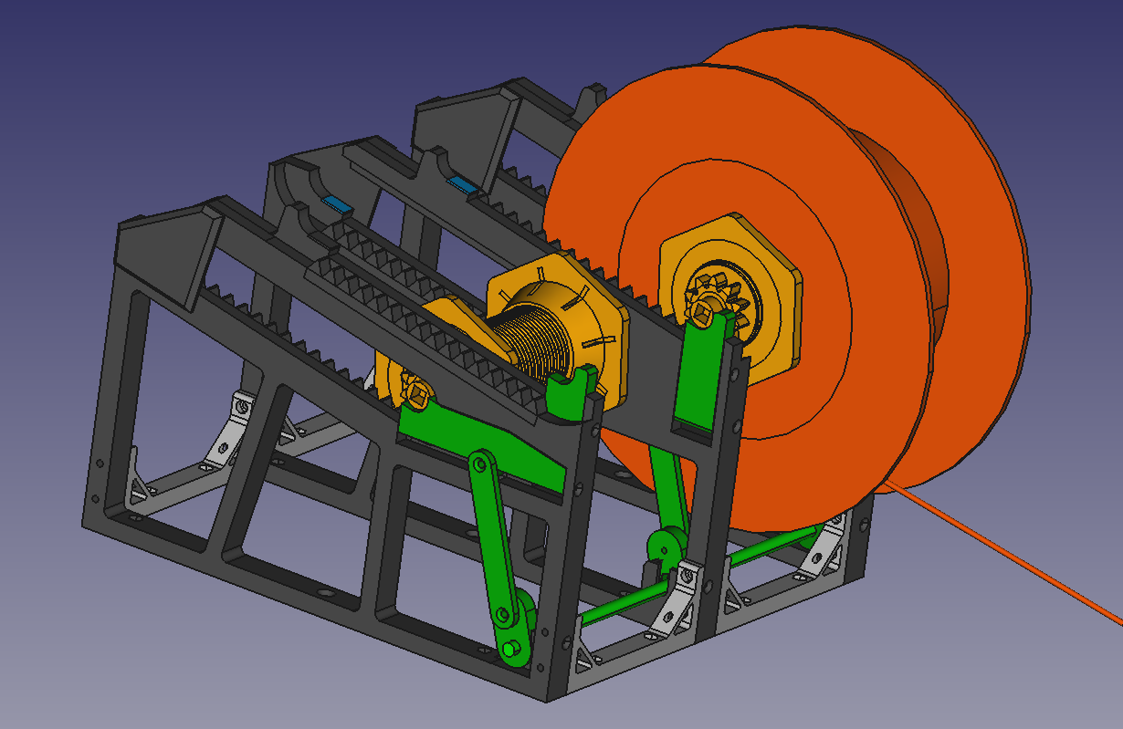
<p>Based upon the fantastic “gravity spool holder” design by Michal Fanta, I developed a compact fivefold setup to mount on top of the LACK enclosure. Added de-clunking (silencer) pads (BLUE in images) and a freewheeling gizmo (GREEN in images) for good measure.</p><p><strong>Concept</strong></p><p>In general terms, I kept the parameters of Michal’s design (slope, length, gear ratio). The spool axle nut would not fit any of my spools, so I chose a slightly larger diameter and added an optional TPU gasket for huge spools. </p><p>When you allow for 80mm wide spools, the whole setup will only fit onto the Lack enclosure if the walls between adjacent compartments incorporate the fittings for the spools on both sides. The resulting “staggering” adds both to the required length and height, but in the end it is possible to fit the design on the Mk3 print bed.</p><p>To be able to lift the spool from the gear rack on the lower end (freewheeling) and let it roll clear of the gear rack on the higher end (de- clunking), the hub ends need to have both a gear and a (smaller) axle.</p><p>The freewheeling mechanism lifts all five spools simultaneously. It needs some fine-tuning (see the “Assembly” section), but makes filament insertion much more comfortable. The lever to operate the mechanism may be placed on either side of the setup.</p><p><strong>Status</strong></p><p>I have completed the design with components in different stages of development and am currently putting it through its paces. Having upgraded the extruder path to 3mm ID, the MMU2 finally works without interventions. Should be included in the kit! The first “wall / lifter”- combo with soluble support looks and works great with absolutely minimal rework. </p><p>The next steps are:</p><p>Complete this article with photos</p><p>Add more project files, calculate time and material</p><p><strong>Change log</strong></p><p>2021-07-18: Added a vertical guide to the lifter.</p><p>2021-07-19: Shortened the ridges in the nut gasket.</p><p><strong>Printing</strong></p><p>You need the following printed components (PETG unless specified otherwise):</p><figure class="table"><table><tbody><tr><td>Count</td><td>Component</td></tr><tr><td>3</td><td>WALL</td></tr><tr><td>3</td><td>WALL (mirrored)</td></tr><tr><td>3</td><td>LIFTER</td></tr><tr><td>3</td><td>LIFTER (mirrored)</td></tr><tr><td>10</td><td>SPACER</td></tr><tr><td>5</td><td>LEVER</td></tr><tr><td>1</td><td>LEVER_VANE (mirrored if you want to have it on the right hand side)</td></tr><tr><td>10</td><td>RUBBER_PLUG (TPU, for de- clunking)</td></tr></tbody></table></figure><p> - additionally, per spool:</p><figure class="table"><table><tbody><tr><td>Count</td><td>Component</td></tr><tr><td>1</td><td>ROLLER</td></tr><tr><td>2</td><td>NUT</td></tr><tr><td>2</td><td>GEAR</td></tr><tr><td>(2)</td><td>GEAR_GASKET] (TPU, for spools with large holes)</td></tr></tbody></table></figure><p>The total printing times and material amounts are</p><figure class="table"><table><tbody><tr><td>Count</td><td>Components</td><td>Time/h</td><td>Material/kg</td></tr><tr><td>6</td><td>Walls/Lifters </td><td>60</td><td>0,720</td></tr><tr><td>5</td><td>Axles/Nuts</td><td>42</td><td>0,450</td></tr><tr><td>1</td><td>Levers/Arms</td><td>3,5</td><td>0,040</td></tr><tr><td>1</td><td>Spacers</td><td>7,3</td><td>0,080</td></tr><tr><td>1</td><td>Rubber parts</td><td>1,5</td><td>0,015</td></tr></tbody></table></figure><p>Most components may be printed with the “0.2mm SPEED” setting at 10% infill. Roller, gear and nut should be printed with a “QUALITY” setting, 0.2mm seems to be good enough for the thread.</p><p>It is possible to print the walls and lifters using single material supports, but the interface layers stick to the body, effectively adding to its height and giving it a rough surface. I removed one or two layers from the prototypes using a milling machine or a sharp chisel, but the results are a bit sub-standard. Printing with soluble support is exact and yields much better surfaces.</p><p><strong>Accessories</strong></p><p>You need the following additional components:</p><figure class="table"><table><tbody><tr><td>Count</td><td>Component</td></tr><tr><td>1</td><td>Base plate (e.g. 8mm plywood, 550 * ~300mm)</td></tr><tr><td>24</td><td>M3x16 countersunk bolt (adjust length for different base plate)</td></tr><tr><td>6</td><td>3.5x30mm (approx.) chipboard screw (to mount plate on enclosure)</td></tr><tr><td>12</td><td>M3x20 panhead bolt</td></tr><tr><td>36</td><td>M3 nut</td></tr><tr><td>12</td><td>M3x10 countersunk bolt</td></tr><tr><td>8</td><td>M3x20 countersunk bolt</td></tr><tr><td>1</td><td>M6 rod (stainless)</td></tr><tr><td>18</td><td>M6 nut (stainless)</td></tr><tr><td>6</td><td>M6 washer</td></tr></tbody></table></figure><p><strong>Assembly</strong></p><p>The threaded holes on the lower vertical side of the WALL components are quite tight. If you own an M3 thread cutter and a cordless drill, use these to ease insertion of the bolts.</p><p>The holes for the “de-clunking” rubber plugs need some rework, especially on the upper side. The goal is to align the rubber surface with the surface behind it, there should be no detectable ledge. Use a small file to grade the upper surface down a bit, check frequently with the rubber plug installed.</p><p>Assemble the walls and spacers with M3x20 panhead bolts and nuts. Alternate“normal” and “mirrored” walls. The outer walls should have the lower gear rack pointing outwards (so you get three upper spools at pos. 1, 3, 5 and two lower ones at pos. 2 and 4). </p><p>Fasten the whole setup on the mounting plate with M3 countersunk bolts all around. Slide the lifters in and fix them with the upper (M3x10, horizontal) and fore (M3x20, vertical) countersunk guide bolts.</p><p>The freewheeling operating mechanism is made of standard, off-the-shelf components, but it is a bit of a bugger to assemble. The best way I found to do it is:</p><ol><li>Get a good quality (stainless, to avoid bending and torsion) M6 rod and cut it to size (~550mm).</li><li>Equip the six levers (five normal ones and a special one with a vane) with M6 nuts.</li><li>Thread twelve nuts (n,N), six levers (L) and six washers (W) onto the rod (roughly to their intended position), possibly using a cordless drill. Make sure that the closed sides of the levers face a washer/nut combo (to lock them in place later on). Use the following lineup:<br> n-L-W-N-----N-W-L-n-----n-L-W-N-----N-W-L-n-----n-L-W-N-----N-W-L-n<br>Note that the nuts marked “n” (the ones without washers) are used as bearings – to prevent the threaded rod from working its way into the plastic.</li><li>Make sure that the vane on the special lever points outwards AND towards the high end of the spool holder when assembled (otherwise “mirror” the print). It may be installed on either end of the assembly. Mount and secure this lever using thread locker fluid (e.g. Loctite 243) on the nut inside the lever and the nut with the washer next to it (NOT the bearing nut!), tighten firmly.</li><li>Fine-adjust the positions of the levers using the low side of the spool holder as a gauge. When in doubt, put them a bit towards the spool side (loose) rather than towards the “bearing” nuts. Secure the levers by hand-tightening the adjacent nut/washer combo.</li><li>Put the whole setup on the edge of a solid workbench and align the levers by clamping them down (individually or all at once with a solid bar).</li><li>Tighten the levers firmly with the “washer” nuts.</li><li>Position the “bearing” nuts approx. 0.5mm (half a revolution) from the levers.</li><li>Screw the lever arms onto the levers (M3x10 countersunk bolts).</li><li>Hold the assembly next to the lower edge of the spool holder so the levers point upward. Turn all the lever arms so they face the higher edge and point downward at approx. 45 degrees.</li><li>Press down on the “bearing” nuts and slide them into the recesses of the spool holder. Be patient, this may take several attempts.</li><li>Secure the outer bearing nuts with two M3x20 countersunk bolts.</li><li>Screw the lever arms to the sliding “lifters” (M3x10 countersunk bolts).</li></ol><p>I may take some photos of the process if I can motivate myself to disassemble the mechanism first..</p><p>At last, fasten the base plate on the Lack enclosure using chipboard screws on the left and right side. Mount the PTFE tubes on the rear top side, e.g. with an aluminium bracket and pneumatic joints.</p><p>You did it! I hope you enjoyed the creative process as much as I did!</p><p>BTW - my wife thinks this design should be called the “Big Ben clockwork” - wheels and gears all over the place (fewer bells, however). <br><br> </p>
With this file you will be able to print Gravity Feeder for Lack Enclosure with your 3D printer. Click on the button and save the file on your computer to work, edit or customize your design. You can also find more 3D designs for printers on Gravity Feeder for Lack Enclosure.