Gnatty-Light Electric UV Bug Catcher
prusaprinters
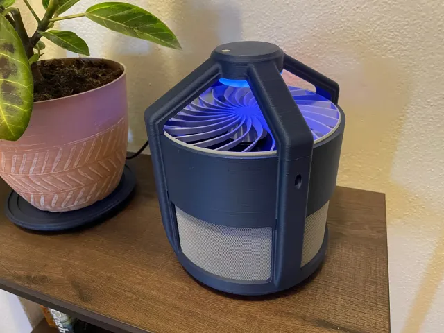
Introducing the Gnatty-Light UV Electric Bug Catcher. The device is powered by 5vdc mini USB and uses an array of UV LEDs and a computer fan to lure, capture, and trap flying pests on a sticky glue pad in the base. Arduino Nano controller allows mode selection between always-on and auto-on at night when dark. UV LEDs are programmed to fade in/out for extra pizzazz. Utilizes standard round glue boards up to 5.5 inch diameter.Why buy a commercial product when you can spend twice the cost making your own. All housings, including mesh screens can be 3D printed on a build plate 200x200mm or larger. Power demand: 5vdc, 0.50 ABOM:All 3D printed partsElectronics:1x Arduino Nano or clone1x RFP30N06LE MOSFET or equivalent logic level devicehttps://www.amazon.com/dp/B07WR86ZGS?psc=1&ref=ppx_yo2ov_dt_b_product_details1x Mini USB breakout boardhttps://www.amazon.com/dp/B07X86RZG3?psc=1&ref=ppx_yo2ov_dt_b_product_details2x sets of 5 pin headers (included with Mini USB breakout boards linked above)1x Computer fan, 120mm x 25mm, 5vdc, 2 wirehttps://www.amazon.com/dp/B00G05A2MU?psc=1&ref=ppx_yo2ov_dt_b_product_detailsNo need for the inline fan speed controller, cut away.Repurpose antivibration mounts as feet screwed into the assembly base.18x UV LEDshttps://www.amazon.com/dp/B077X8P33G?psc=1&ref=ppx_yo2ov_dt_b_product_details18x 100 Ohm resistors, 1/4W (for UV LEDs)3x 10 kOhm resistors, 1/4W (Arduino pulldown)1x USB A to Mini USB cablehttps://www.amazon.com/dp/B002KL8J8W?psc=1&ref=ppx_yo2ov_dt_b_product_details1x Mini USB cable (sacrificial for the connector, often included with Arduino clones)ON/OFF/ON 6-Pin DPDT 3-Position Snap-In Rocker Switchhttps://www.lizardleds.com/5x-on-off-on-6-pin-dpdt-3-position-snap-in-rocker-switches-ac-6a-250v-10a-125v/mp/100025961x Red LED (power indicator)1x 150 Ohm resistor (for power indicator LED)Generic 5mm dia photoresistor3x pairs of JST conectors (optional for ease of connecting LED board, photoresistor, and fan to Arduino board)USB A wall power adaptor (phone charger brick)Several feet of 24 AWG wire, shrink sleeve, and solder etc.Hardware4x 5mm x 8mm screws (attach top_grill) to fan4x 4mm x 20mm screws (attach mid_upper housing to lower_housing)5x 4mm x 12mm screw (attach LED board to top_main, and attach fan to mid_upper housing)6x 4mm x 8mm screws (attach funnel to mid_upper housing, and attach arduino board to funnel)4x 3mm x 12mm screws (attach mid_upper housing to top_main)6x 3mm x 8mm screws (attach mini USB board to electric panel, and attach electric panel to mid_upper housing)8x 0.25 inch neodymium magnets (inside base and mid_lower housing to snap together)4x anti-vibration feet for the base, repurposed from the computer fan linked above.3mm, 4mm, 5mm tapsSuperglueRound glue boards up to 5.5 inch diameter.Printing Notes:See individual file notes for specific advice.All models are optimized for and printed at 0.2mm layer hight, 0.40mm line width, with a 0.4mm nozzle.Base and mid_lower housing contain embedded magnets and require pause at layer height to insert during printing.All housings and mesh are printed with PLA of your desired color. I used Polymaker Matte Army Blue and Overture Matte Grey.Photosensor cover, LED diffusor, and Arduino board are printed with clear PETG.Several models include a one layer solid over the begining of holes printed down for clean circles without supports. Open up with drill or knife after printing.Total filament weight is -750g. Assembly Notes:Clean out all screw holes and tap all threaded holes. Note: use super glue as thread locker during assembly. See hardware list above for screw size usage.Tap the 4x mounting holes on the top side of the fan with 5mm tap.Top Main subassemblyLED Board Install all LEDs. Bend of the LED wires on the back side as shown in LED board schematic and solder together in parallel. Trim excess leads.Arrange and solder 100 ohm resistors to LED leads.Solder 18" length of wire to LED array.Glue photoresitor into clear housing. Bend leads to the side and slder 18" of wire to leads. Press into top_main hole and glue around edges to retain. Feed wires down top_main hollow channel.Feed LED board wires down top_main hollow channel on same side as LED board wires. Attach LED board to top_main boss with 1x screw.Align diffusor tabs and snap into place over the LED array.Controller SubassemblyGlue Aruino to makeshift breadboard (optionally fasten corner mounting holes to breadboard with makeshift rivets make from filament warmed and stretched to ~1.5mm diameter. Insert, heat each side with a lighter, and smush to retain).Install and solder electronics as shown in schematic and photo. Leave long lengths of wires for interfacing with the electric panel later.See photo for reference. This is a major pain and you may find your own best layout configuration. Keep wires as short and compact as possible to ensure assembly will fit into housing.Test controller subassembly with Arduino sketch before moving on, use breadboard to interface with LEDs, fan, photoresistor, switch etc.Mid Housing SubassemblySlide 4x mesh screens into mid_lower housing channels.Slide mid_lower to mid_upper, ensuring the mesh screens are aligned with their mating channels. Helpful to flip the assembly over and guide from the inside.Attach mid_upper to mid_lower with 4x screws in the side rib pockets. Install funnel into mid_upper housing and retain with 4x screws on the holes offset 45 degrees from the housing side ribs.Install fan on top of funnel with the corners clocked with the housing side ribs and retain with 4x screws via the fan's lower mounting holes. Cut fan wires to 8-12" long, no need to use fan speed controller if built into the cable. Base SubassemblyAttach 4x anti-vibration feet to the holes into the bottom of the base.Main Housing SubassemblyGuide photoresistor and LED board wires into mid_upper channels. Leave a few inches of slack and allow top_main to rest to the side for now.Connect photoresistor, LED board, and fan wires to the controller board subassembly.Feed wires for electric panel out the mid_lower electric panel cutout.Attach controller subassembly to funnel with 2x screws. Tuck wires around perimeter cleanly.Install top_grill and attach to fan with 4x screws.Install top_main onto mid_upper, tucking wires through the passthrough holes, and attach with 4x screws from the outside pockets.Attach base to mid_lower with embedded magnets aligned (watch your fingers).Electric Panel SubassemblyInsert Mini USB breakout board with pin headers into panel slot (solder to controller wires to header pins if not done already). Retain with 2x screws.Install power indicator LED with into hole (solder resistor to lead if not done already)Feed power and mode select wires through switch cutout. Solder to switch.Snap switch into panel cutout and glue back side to retain if needed.Tuck mid housing internal wires to the sides to make room for panel installation.Install panel onto mid housing cutout and attach with 4x screws.CompleteMini USB port provides power connection and interface with Arduino for future programming mods.Put your favorite sticky glue pad in the base and your ready to catch some bugs. Most effective at night.Two switch modes allows always-on, or nightime only auto-on functionality.
With this file you will be able to print Gnatty-Light Electric UV Bug Catcher with your 3D printer. Click on the button and save the file on your computer to work, edit or customize your design. You can also find more 3D designs for printers on Gnatty-Light Electric UV Bug Catcher.