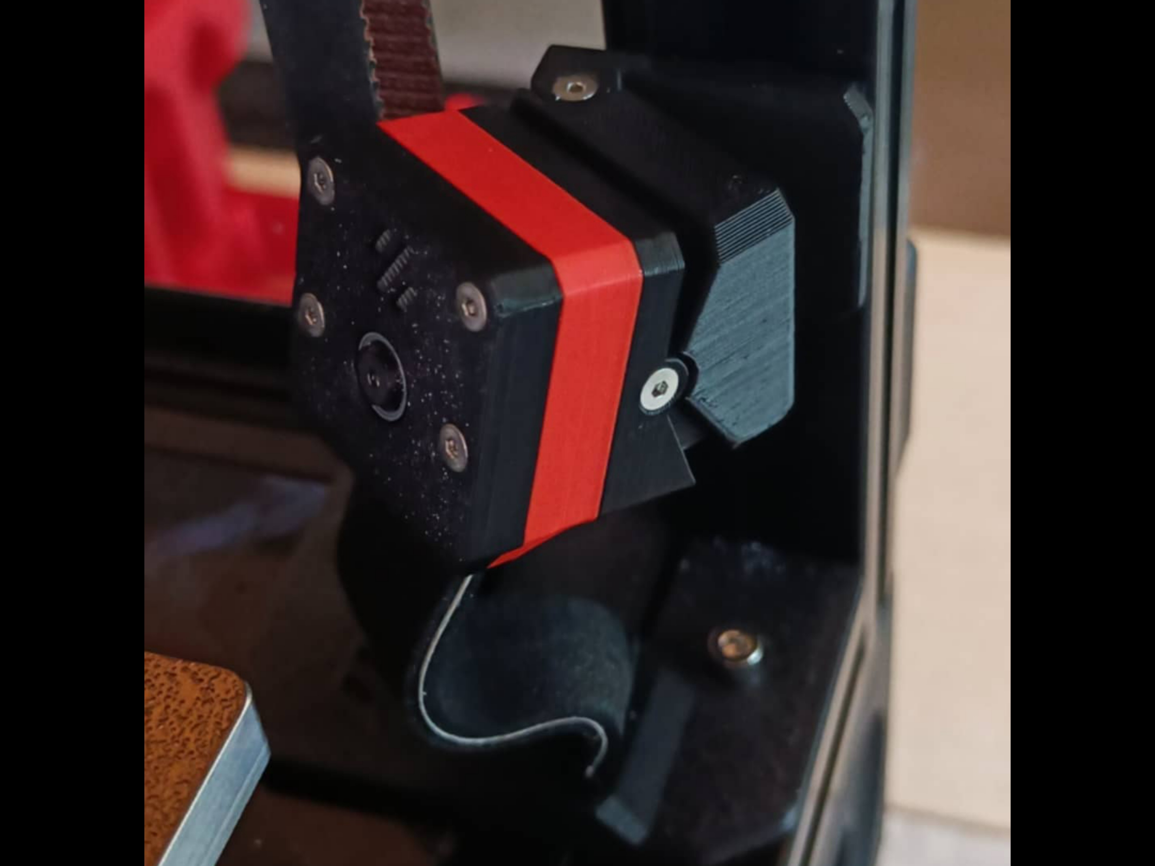
GLaDOS Cam
prusaprinters
<p><i><strong>WARNING: The current version might have the Stealthburner bump into it at max travel points (not in regular printing area)</strong></i></p><p><i><strong>______________________________________________________________________________________________________________</strong></i></p><p><i><strong>Introduction:</strong></i></p><p>Minimal setup for surveillance of any printer using a 2020 extrusion as frame.</p><p>It has adjustable angles of 30° vertical and 45° horizontal.</p><p>It uses small screws and embedded magnets for alignment and attatchment.</p><p>I made this for my VORON 2.4.</p><p><i><strong>______________________________________________________________________________________________________________</strong></i></p><figure class="table" style="height:178.891px;width:714px;"><table style="background-color:rgb(255, 255, 255);border:3px ridge rgb(0, 0, 0);"><tbody><tr><td style="background-color:rgb(250, 104, 49);border:1px solid rgb(191, 191, 191);padding:0.4em;vertical-align:top;"><strong>HARDWARE</strong></td><td style="border:1px solid rgb(191, 191, 191);padding:0.4em;vertical-align:top;"><i>Q.ty</i></td></tr><tr><td style="border:1px solid rgb(191, 191, 191);padding:0.4em;vertical-align:top;"><strong>FHCM2x10[mm]</strong> flat head screws for the camera housing and arm asembly.</td><td style="border:1px solid rgb(191, 191, 191);padding:0.4em;vertical-align:top;"><i><strong>7x</strong></i></td></tr><tr><td style="border:1px solid rgb(191, 191, 191);padding:0.4em;vertical-align:top;"><strong>FHCM3x6 or 8[mm]</strong> flat head screw to fix the arm to the frame.</td><td style="border:1px solid rgb(191, 191, 191);padding:0.4em;vertical-align:top;"><i><strong>1x</strong></i></td></tr><tr><td><strong>M3 Hammer Head T-nut</strong> to fix the arm and z belt guard to the frame.</td><td><i><strong>4x</strong></i></td></tr><tr><td><strong>6x3[mm] Magnets (VORON BOM)</strong> for camera-arm interface.</td><td><i><strong>4x</strong></i></td></tr><tr><td><strong>Foam Tape</strong> to protect the ribbon cable.</td><td><i><strong>-</strong></i></td></tr><tr><td><strong>SHCM3x6 or 8[mm]</strong> socket head screws to fix the Z belt guard.</td><td><i><strong>3x</strong></i></td></tr></tbody></table></figure><p>________________________________________________________________________________________________________________</p><figure class="table" style="height:144.125px;width:714px;"><table style="background-color:rgb(255, 255, 255);border:3px ridge rgb(0, 0, 0);"><tbody><tr><td style="background-color:rgb(250, 104, 49);border:1px solid rgb(191, 191, 191);padding:0.4em;vertical-align:top;"><strong>Slicing Instructions</strong></td></tr><tr><td style="border:1px solid rgb(191, 191, 191);padding:0.4em;vertical-align:top;"><i><strong>Material:</strong></i> Required ABS/ASA or better</td></tr><tr><td style="border:1px solid rgb(191, 191, 191);padding:0.4em;vertical-align:top;"><i><strong>Layer Height:</strong></i> 0.2 [mm]</td></tr><tr><td><i><strong>COLOR CHANGE:</strong> at 3,6 [mm] for embedding magnets.</i></td></tr></tbody></table></figure><p><i>I recommend printing the arm first, since it takes longer, it's best to get it right the first time.</i></p><p>________________________________________________________________________________________________________________</p><p><i><strong>Embedding Magnets:</strong></i></p><p>Start your print, then make a pile of 4 magnets and take 2 out one at a time, placing them in their holes in the same orientation at color change. Then resume and let the print finish.</p><p>When it's finished, DO NOT yank it off the plate. Let it cool and detatch, otherwise the magnets will damage the single layer they're sitting on.</p><p>Once you have your mount, take the remaining 2 magnets and attatch them to the interface piece.</p><p>Keep the piece handy and when it's time, take the 2 magnets off the mount and before inserting them in the holes, PAY ATTENTION TO THEIR <strong>POLARITY</strong>.</p><p>If all goes well, when both magnetic parts are finished they should couple without issues.</p><p>________________________________________________________________________________________________________________</p><p><i><strong>Assembly:</strong></i></p><p><i><strong>- Camera Arm:</strong></i></p><ul><li>Assemble as shown in the pictures. Do not overtighten, or you'll shred the holes.</li></ul><figure class="image image_resized" style="width:85.04%;"><img src="https://media.printables.com/media/prints/138904/rich_content/03d85475-6e03-402d-ab51-7222f009bc0a/inst.png#%7B%22uuid%22%3A%221092e9c3-3142-4a0e-b267-8a84ed4fbff5%22%2C%22w%22%3A1279%2C%22h%22%3A720%7D"></figure><ul><li>This is optional. If your printer resonates a lot or you just want to be extra fancy, apply some foam tape as shown.</li></ul><figure class="image image_resized" style="width:85.19%;"><img src="https://media.printables.com/media/prints/138904/rich_content/9b7c8189-cb33-4274-9e87-98fab86dc563/tape.png#%7B%22uuid%22%3A%220275ce20-b15e-42de-bcf5-b516be4b2325%22%2C%22w%22%3A1279%2C%22h%22%3A720%7D"></figure><ul><li>Prepare the M3 bolt and the T-Nut. Before fixing the arm to the frame. <strong>BE CAREFUL of WHERE you fix it</strong>. I recommend you do this after homing your printer, if equipped with a flying gantry.</li></ul><p> </p><p><i><strong>- Camera Housing:</strong></i></p><ul><li>Take your ribbon cable and protect it with some sort of tape. I used KAPTON along the whole ribbon and foam tape on the exposed part going to the camera.</li></ul><p><i><strong>- ---FOR VORON 2.4: </strong>Try to insert it through the deck panel directly, or via one of the Z belt holes. If you can't, try to make your way in by using some sort of spacing tool.</i></p><p><i>If you still can't, use the spacing tool to insert some sandpaper between the estrusion and deck panel, and make some space. </i></p><figure class="image image_resized" style="width:85.1%;"><img src="https://media.printables.com/media/prints/138904/rich_content/017ae336-35f0-4fd9-a343-bc38717820a5/ribbon.png#%7B%22uuid%22%3A%226adcb7af-a7d4-4e9d-b825-8aace1a9d97b%22%2C%22w%22%3A1279%2C%22h%22%3A720%7D"></figure><p><i>Then carefully insert the cable into the Z belt guard and fix it in place.<strong>---</strong></i></p><ul><li>Secure the ribbon cable into the Pi Cam, and palce the camera in the Front Housing. Sandwich it between the front and back housing, then thread in the screws until the heads are flush with the surface.</li></ul><figure class="image image_resized" style="width:85.19%;"><img src="https://media.printables.com/media/prints/138904/rich_content/7b5ac4ec-02d4-4c1d-b3b0-3e70012dcfaa/cam.png#%7B%22uuid%22%3A%22573c193e-0118-49f7-b461-4c95539c4358%22%2C%22w%22%3A1279%2C%22h%22%3A720%7D"></figure><ul><li>Lastly, just drop it on the arm and it'll magnetically attach.</li></ul><p>________________________________________________________________________________________________________________</p><p><i><strong>Adjusting & Testing:</strong></i></p><ul><li>Angle the camera and tighten screews if needed, check that your cable is not too tense, check your camera view and adjust height if needed, then set the focus with the provided Pi cam tool.</li></ul><figure class="image image_resized" style="width:85.1%;"><img src="https://media.printables.com/media/prints/138904/rich_content/68cadf1d-6db1-44e4-b92e-ac68d2e5401b/done.png#%7B%22uuid%22%3A%2263bdb8f9-c398-4e00-9e86-546e1243cfff%22%2C%22w%22%3A1279%2C%22h%22%3A720%7D"></figure><ul><li><strong>DONE!</strong></li></ul><p><i><strong>______________________________________________________________________________________________________________</strong></i></p><p><strong>VARIATIONS</strong></p><ul><li>Given the symmetry of the camera housing, you can easily fix the arm anywhere in your printer. this is useful for trident printers, where you can easily mount it on top of a vertical extrusion, pointing it down. You may need to mirror the arm STLs.</li></ul><figure class="image image_resized" style="width:85.19%;"><img src="https://media.printables.com/media/prints/138904/rich_content/6b5d8d3f-36a1-4382-b4e8-fbe5a961fbe4/dim.png#%7B%22uuid%22%3A%2268b810e2-46b6-4560-abb9-a205b594cadf%22%2C%22w%22%3A1279%2C%22h%22%3A720%7D"></figure><ul><li>Interface dimensions. with these, you can design your own arm or camera housing. Please notify me if you remix it or if you want your STLs to be uploaded here. I will credit you.</li></ul><p><i><strong>______________________________________________________________________________________________________________</strong></i></p><p>Feel free to <strong>post your makes</strong>, feedback is highly appreciated. </p><p>Loosely inspired from <a href="https://github.com/VoronDesign/VoronUsers/tree/master/printer_mods/richardjm/picam-corner">this mod</a> by RichardJM on GitHub.</p>
With this file you will be able to print GLaDOS Cam with your 3D printer. Click on the button and save the file on your computer to work, edit or customize your design. You can also find more 3D designs for printers on GLaDOS Cam.
