Ghost Clip
prusaprinters
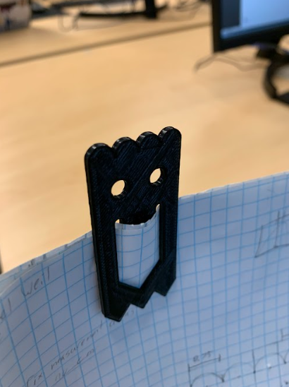
<p><strong>Summary Continued: </strong></p><p>It’s easy to make and small enough to fit in your pocket and take it anywhere you go with dimensions of 6.5 cm x 3.0 cm x 0.2 cm.</p><p>Link to my partner’s page:</p><p> </p><p><strong>Lesson Plan Activity:</strong><br> </p><p>For this project, our task was to recreate a 3D printed ghost clip while focusing on collaboration and accuracy. </p><p> </p><p><strong>How I Designed This:</strong></p><p><br>The first step in designing our ghost clips was sketching them. My partner and I, used pencils, rulers, compasses, and graph paper in order to create an accurate representation of the ghost. Our sketch was scaled to twice the size of the real ghost clip, but the measurements we wrote on it were scaled one to one. This allowed the sketch to be more accessible while the measurements still being accurate. The one rule was we could not trace the ghost, but had to recreate it in other ways. The first step to sketching was drawing a constraint box which was the outermost part of the ghost in the shape of a rectangle.</p><figure class="image image_resized image-style-align-center" style="width:75%;"><img src="https://lh3.googleusercontent.com/_MoQs8IK7_UuhiHes0TJXd0rKcGF8JoaXdgC4eFdPdveMlv3MTco9GTCuw98RT5FucXdnF45M6dF6CwGCUDfpy0fgzUkZyYIUwYD1OJnLDOLl_h4XCzvuEEeEMLAmEdVHo6Wu6p1XT2jVP8MbwO3AKHnOIFjx0WIEzVbJsoXVnUNclK_1yZsuNZbtQ"></figure><p>The rest of the sketching process consisted of measuring the ghost and translating it to our papers.</p><figure class="image image_resized image-style-align-center" style="width:75%;"><img src="https://lh4.googleusercontent.com/RNX7f7wUH-Oxpqw6EAVKQRZcshFPL_4jkm3ytZ0IjGR5Y0sLAsikQCXEpfhSYdX0J1qxy6vxKKD9-nxt121m_NqgWXYXb3lpzDUtU61wLRhewZG8qMlsVhjE3uYogBLcOKwl6ET87AmYbmKyHPk6MoJ2HuCSui3Xz9PbP_IrtSVQc8pJN0q2cxg7Vg"></figure><p>After finalizing our sketches, we made a step-by-step plan on how to transfer our sketch to Solidworks, a 3D printing software.</p><figure class="image image_resized image-style-align-center" style="width:75%;"><img src="https://lh3.googleusercontent.com/gIy57dq5uePqdl_ksw6QFkDbRSZP5BzJ3uRoNXaVXHpEAQyAdHPLLDUhFuNe7cii4BWeI7xT9Re0c31edESqRUEQv4Uth9ixDkxQkWekl_1xoupzP2uiLSu3YuWvFDDWMQ1rZAWgU_wGEsu-ach49eFyavpE7x_gg77C47Mv_5o5ORaHyAwhTBmDDQ"></figure><p>Once that was finished we moved to the computers to start creating the Solidworks sketch. This step was completed by simply following the instructions we had made for ourselves and going click for click with each other to make sure our projects matched. The outline guided us in creating the right half of the ghost. This allowed us to take advantage of the mirror entities feature on Solidworks. With just the click of a button, our half created ghost was a full ghost.</p><figure class="image image_resized image-style-align-center" style="width:75%;"><img src="https://lh6.googleusercontent.com/qFWFcXc81P_fR_PVDZ1_2-tRNcnHf5Kvqr0DmMXnCp85mMt-ti-ib4ECyrTbYcztXIz0tvJLRJHgWjfQ3cT_ifKNxgbslA4yZvkwVFX_kGh_aYBFylWe_uTmg1w1T2uJLIAsYPFY4JTTMVplOAqmUDynndvuJmHeGlfWsIeRzVB2-NpQV14INPDs0Q"></figure><p>Creating the sketch on Solidworks was followed by lining up the sketch on the computers to the real ghost clip and fixing any minor differences. This was done by placing the original ghost clip on the sill of the computer and sizing down our sketch so they lined up which made it easier to notice the faults. The first issue we noticed was the placement of the eyes in that they were too far apart on our sketch. To fix this, we lengthened the construction line between the center of the eye and the right wall of the constraint box from 0.80 cm to 0.85 cm therefore bringing the eyes closer together.</p><figure class="image image_resized image-style-align-center" style="width:75%;"><img src="https://media.printables.com/media/prints/298748/rich_content/aa45f4c5-cdaa-4d7a-bdfe-788a6b6110f5/image.png#%7B%22uuid%22%3A%227c3cfc01-7de4-438d-b981-88a5640f0362%22%2C%22w%22%3A404%2C%22h%22%3A118%7D"></figure><p>Next, we realized the eyes were too large so we reduced the diameter from 0.75 cm to 0.58 cm. These were both aesthetic changes to make the clips more identical.</p><figure class="image image_resized image-style-align-center" style="width:75%;"><img src="https://media.printables.com/media/prints/298748/rich_content/34cdcc2b-2a91-4578-a6e7-1e8326762b2e/image.png#%7B%22uuid%22%3A%228639e50e-7bcb-4f28-905f-07d23e9918bc%22%2C%22w%22%3A403%2C%22h%22%3A127%7D"></figure><p>The last issue was the mouth being too high. This was an easy fix as all we had to do was lower the bottom anchor point of the mouth by 0.1 cm and it brought the rest of the mouth down with it due to the feature being fully defined. This was a functional change because the mouth is the part of the clip that holds materials together.</p><figure class="image image_resized image-style-align-center" style="width:75%;"><img src="https://media.printables.com/media/prints/298748/rich_content/a0e2c7f0-ee27-4165-8567-786c1745c204/image.png#%7B%22uuid%22%3A%2207ec3727-f3b1-4792-9762-59635bbe9d24%22%2C%22w%22%3A403%2C%22h%22%3A139%7D"></figure><p>After reviewing and finalizing the sketch on Solidworks, there were only a few steps left to do. Most importantly, we had to extrude the sketch, or make it three dimensional. The extrude boss/base tool allows a sketch to become 3D so we extruded our sketch by 0.20 cm. The final step was engraving our initials. First we sketched them on the front face of the ghost.</p><figure class="image image_resized image-style-align-center" style="width:75%;"><img src="https://media.printables.com/media/prints/298748/rich_content/ddfaaac2-f31d-403b-8154-1b580b8b0716/image.png#%7B%22uuid%22%3A%22edd711e1-2d1e-48fe-8407-cc181fbdc36a%22%2C%22w%22%3A204%2C%22h%22%3A166%7D"></figure><p>Using the extruded cut feature, we engraved them into the ghost with a depth of 0.10 cm. This left us with our final model of our ghost clips.</p><figure class="image image_resized image-style-align-center" style="width:75%;"><img src="https://lh6.googleusercontent.com/vVI0tiDil7EznuyQn5h1aR44k_PJ0lMu1Jmuk8xxN9aK2EtDkQVaV1zvT7s5Cc-boWM8fFGqJO4vg3iCutUcaRfJLvTjjRhU5EddR8SbqLJFdOoLWyA5rhGDIlnpxkUmbKgf9A9dXSO5Yny_4gIumIlKu2IEM7y9njgdt1FO6715WRpJXT1S0j8xqA"></figure><figure class="image image_resized image-style-align-center" style="width:75%;"><img src="https://lh6.googleusercontent.com/XUip_7f26TtElEjIqzXWU6L3CKpj4-TfsueGbthGHrgxSt-Z-XYL7X6i3wNXHplniBSgQ8LBrwPMDMfySqbKev7ySLnymsuVylfgSS1KDawRCk0xaGpyVZgHy-CAWUhd7fvxBCDvX5mt8CCFkqWQNszpHiNu3Yoh_SlYPMhKvrOrWUtRxGBwAP4WOg"></figure><p> </p><p><strong>Assembly Instructions:</strong></p><ul><li>Create center rectangle centered on the origin </li><li>Set as construction geometry </li><li>Add smart dimensions to constraint box </li><li>Add construction lines for where arcs and spikes start </li><li>Add construction line for bottom of mouth to lowest point on constraint box </li><li>Set smart dimension for construction lines </li><li>Add construction line for bend on mouth (right side) to constraint box wall </li><li>Set smart dimension for construction lines</li><li>Add construction line for point on top of mouth to construction line for arcs (right side) equal length to previous construction line and 4.3 up from bottom of constraint box</li><li>Add lines for mouth from bottom anchor point to mid anchor point, then mid anchor point to top of the mouth only for right side (set vertical/horizontal as needed) </li><li>Offset on the inside </li><li>Use trim entities to remove extra line </li><li>Add arc on top of mouth </li><li>Add construction line from top construction line for arcs </li><li>Add construction line intersecting with previous line</li><li>Add circle</li><li> centered where the construction lines intersect </li><li>At bottom of constraint box, add a vertical construction line in from right wall </li><li>Add a second vertical construction line off of the previous line </li><li>Connect anchor points in triangles and construction lines </li><li> Inside top constraint box, add vertical construction line from middle line</li><li>Connect arcs from created anchor points</li><li>Mirror over center line so other half of design is filled</li></ul>
With this file you will be able to print Ghost Clip with your 3D printer. Click on the button and save the file on your computer to work, edit or customize your design. You can also find more 3D designs for printers on Ghost Clip.