Ghost Clip
prusaprinters
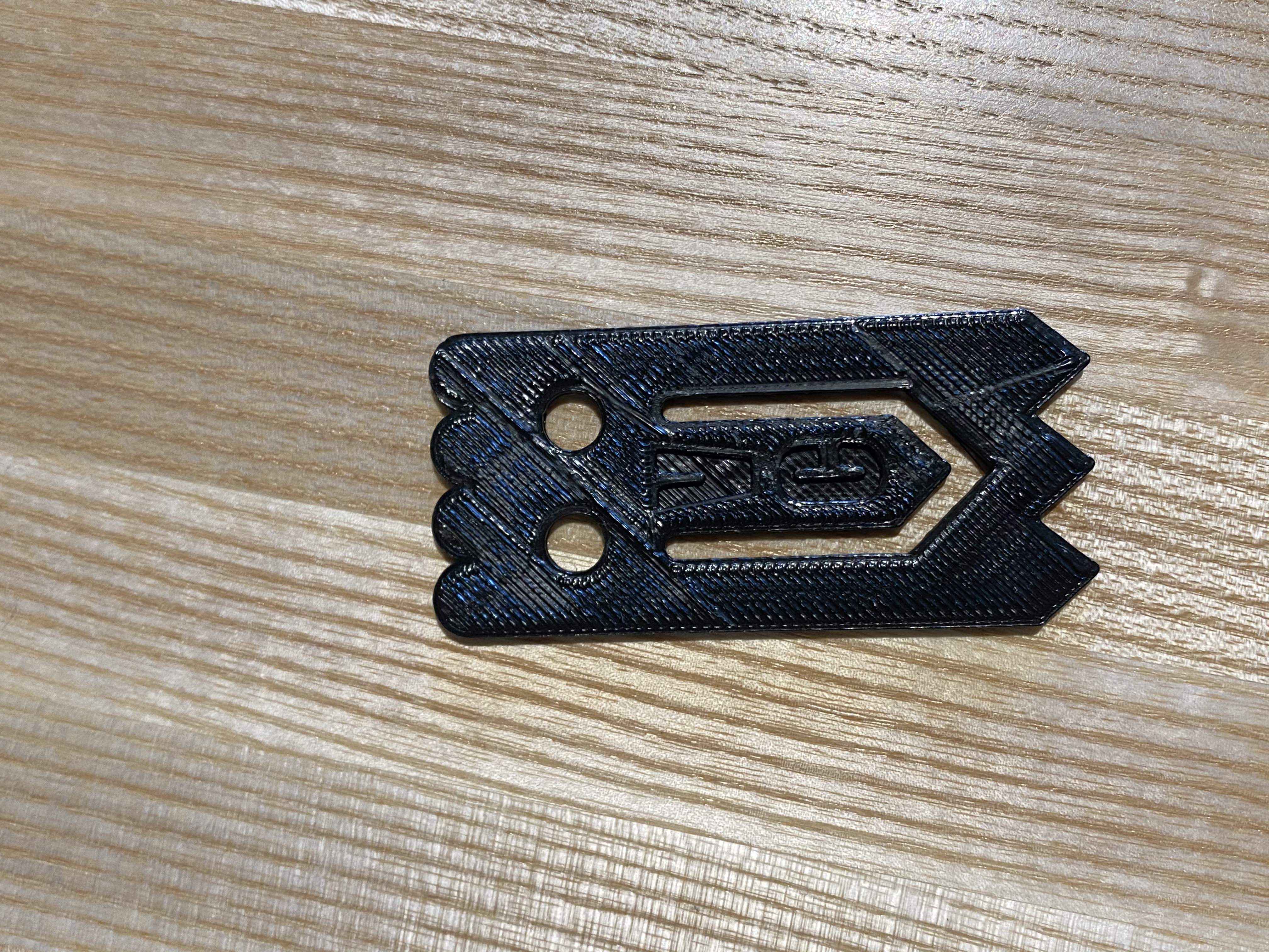
<p>(cont. from Summary) bag clip. This ghost clip is also customizable with your initials! The overall dimensions for this is 3.1cm by 6.66cm by 0.2cm. This was a project made in collaboration with Soham Kulkarni, whose page can be found here: <a href="https://www.printables.com/model/301328-ghost-clip">https://www.printables.com/model/301328-ghost-clip</a> .</p><p><img class="image_resized" style="width:24px;" src="https://ssl.gstatic.com/ui/v1/icons/mail/images/cleardot.gif"></p><p>Project Constraints:</p><p>The project challenged us to create our own copy of the model of the ghost clip given to us in class. Our model and our partner’s model had to be identical to each other and the original model, and we collaborated with our partners by doing every step together. Before printing, the sketch had to be fully defined with no error messages, be inside a constraint box, and have efficient dimensions. We also had to demonstrate the use of offset entities, mirroring, manual relations, and smart dimensions.</p><p><br>Instructions:</p><ol><li>Make a center rectangle off the origin. </li><li>Dimension the box to 3.1cm by 6.66cm.</li></ol><p><strong>Bottom Triangles</strong></p><ol><li>Make reference geometry for triangles on the bottom. <ol><li>start with a construction line 0.6cm up from the bottom of the constraint box and dimension it. </li><li>Then make construction lines for 1.033cm from the right edge of the constraint box, and then more construction lines 1.033cm apart from each other.</li><li>Identify the center of each 1.033cm segment (vertex of the triangles) with points at 0.516cm away from each 1.033cm mark.</li></ol></li></ol><p><br> </p><ol><li>Connect the dots with lines, starting from the intersection of the 0.6cm line and the right edge of the constraint box, in a zigzag fashion until the left edge of the constraint box is reached.</li></ol><p><img src="https://lh4.googleusercontent.com/BG-GBgMhSmvNz9EFT8dITlce6dwwM33gK3QHf2vmh493_cN15_MIcJuhJgG2hWmtVA37goHg8EsVyhANCaXhC0CNjCykgoXWB750z575SJ2_VCZPMPG2AdkN_qa6joU-z46r8Zu4Psefdb33o-mTH48istdGO1dYG2nG36SECbVfYxBkjGb0Ml3r5w"></p><p><strong>Mouth</strong></p><ol><li>Make another reference line 1.8cm up from the bottom of the box</li><li>Make another reference line 0.95cm up from the bottom of the box. Identify the point where this line intersects with the vertical center line.</li><li>Make another reference line 4.13cm up from the bottom of the box.</li><li>Make a vertical reference line 0.7cm from the right side of the constraint box (the line should be between the 4.13 and the 1.8 horizontal reference lines.</li><li>Connect the bottom of the 0.7cm line to the point identified in Step 6.</li><li>Mirror the vertical and diagonal line across the centerline.</li><li>Reverse offset this U shaped series. Turn cap ends on and make the radius 0.175cm.</li><li>Dimension the width of the mouth to be 0.3 cm.</li></ol><figure class="image"><img src="https://media.printables.com/media/prints/300976/rich_content/70cbee73-510b-4107-a140-75ba5ef2e745/image.png#%7B%22uuid%22%3A%2208e4cf25-4573-4cca-aa38-c6520a7a473c%22%2C%22w%22%3A240%2C%22h%22%3A213%7D"></figure><p><strong>Eyes</strong></p><ol><li>Make a horizontal reference line 4.85cm up from the bottom of the box. </li><li>Make another horizontal reference line 5.5cm up from the bottom of the box</li><li>Make a vertical reference line 0.6cm away from the right edge of the constraint box.</li><li>Make a vertical reference line 0.65cm away from the 0.6cm line made in Step 15.</li><li>Notice the rectangle made from the intersections of the reference lines.</li><li>Make a 3pt circle at the center of the rectangle and smart dimension it to have a diameter of 0.65 cm.</li><li>Mirror circle over the centerline to create the second eye.</li></ol><p><img src="https://lh6.googleusercontent.com/73DiV2pBwf11Qzycs5n-6NSoSbj0tFMa8fFvbTWQyaOQfUW21Xfn4MophF-zbSDYfQAiNjo33EBFq3yzktzn0kdM2C74CKwYeOjCRE05vIDUazhoZrSipKD9GAasj22F28aUKo9uZ-EJHsRpKXPn87f6efOUEuK_i-KfJp3u5MHOgb4O7D7ZjIq_Zw"></p><p><strong>Top semi-circles</strong></p><ol><li>Make a horizontal reference line 6.25cm up from the bottom of the box. </li><li>Make a vertical reference line 0.775cm away from the right edge of the constraint box.</li><li>Make a vertical reference line 1.55cm away from the right edge of the constraint box.</li><li>Draw a semi-circle (flat edge on the 6.3cm line) with the endpoints on the right edge of the constraint box and the 0.8cm line. The top edge should be touching the top of the constraint box. The diameter of the semicircle should be 0.775, after smart dimensions.</li><li>Draw another semi-circle (flat edge on the 6.3 line) with the endpoints on the 1.6cm line and the 0.8 line. The top edge should be touching the top of the constraint box. The diameter should be 0.775, after smart dimensions. Set relations to make the two arcs equal.</li><li>Use mirror tool to mirror over the centerline of the constraint box. There should be four semicircles at the top of the clip drawing.</li></ol><p><img src="https://lh5.googleusercontent.com/crQvD-8hZWlyVAC7LSlygsKly1kXLWiaL1WEpHpjO1fl3edPOk-bbrV2gFyDJzPWUStIvRGxg6B1PVzheae8y1YyjYfVc70-MDXSAXrXiL-cdIFXuoQ5v5Ev912xBz6X1m6EzS00fjgfIkQYdoUi6l_9HRgQn-UL6mfC8A3cQC9wB0Hhyq9-qwnAWg"></p><p><strong>Extruding and adding letters</strong></p><ol><li>Extrude boss/base the sketch to 0.2cm.</li><li>Sketch two horizontal lines on the center flap of the clip.</li><li>Click on the lines and add text to it. Change the font to Impact and adjust positioning and size to your desire.</li><li>Indent the two letters to 0.1cm using the extruded cut tool.</li></ol><p><img class="image_resized" style="width:17.51%;" src="https://lh4.googleusercontent.com/S6-hS8AcH5xdllf80OVG_ZTH6EBphFqL8iEl2Ye0aeSEuIWKLG6mRn3IhUk8DBpI70SdqZ9vF0xP30Ls0z03v0XLH8gUssji2Q59L0mYoU7N2NN0SvkQlFsyJN4EMCUUKShtvUhSjZOtTH4Txhjg1WDwKAb25elYGcwE3zPcj4ovCL5pIZNZUbu8GQ"></p><p>Design Choices:</p><p>We first started off by looking at the model and drawing a diagram with 2x the dimensions so each measurement would be easier to see. The numbers labeled on the diagram were the true dimensions, though. Similar to the Solidworks sketching process, we made many reference points before sketching the permanent lines. </p><p><img src="https://lh4.googleusercontent.com/Cd-oJUyNrybSGRBX2myLdHaV5VFlAF_B71mSfdeXTxK1yYzTIaHawwPs_2PFO2PEJ1VSbdgQemm657aO8Fs-tf_o1rm34cfe2jT0J1jAqI_owYImPSKSsbh5n08cR6-PHqjGHQfP3NPaGR5pICgbT4jov58cqM7ptpTSuAtG8MPFolz5is88lCgzIA"></p><p><br> </p><p>My partner and I measured the model clip with a centimeter ruler, and when we couldn’t agree on a value, we took the average of our estimates. Something that made it hard to measure was definitely that the model clip had curved sides, blurring the lines between the absolute edge and the start of the top flat edge. </p><p><br><br> </p><p><img class="image_resized" style="width:31.89%;" src="https://lh3.googleusercontent.com/qrhv2BM9dhirSNtaYSWenwcqkHrwM-fH0aW_Lf3PbtqHzPtHQsWQAi8_sf838rmLe4IjYVTLfWR5aF_0BWct7VdWWumHyv-KTvd4VOet8whPJOoY4TzufpiYhuuHbpLlYg26B_52pNCv5JoPKQ-X_YmPQcdfLoUAn185nxSW5HEd3E4gOf1_FtshWA"></p><p>Slightly curved edge on the original model</p><p>Like the process for the paper sketch, in Solidworks, we also made a lot of reference lines before drawing the actual structure. Some dimensions on the paper were later changed on the computer when we realized that all the vertical or horizontal segment lengths needed to add up to the same value. For example, on the paper, the top bumps added up to be 3.2 centimeters, whereas the bottom triangles added up to be 3.3 centimeters. Such a difference normally would not matter on paper, but when setting the dimensions of the constraint box, total length needed to be uniform throughout. For that particular issue, we measured the clip again, and if there were further discrepancies, we rounded to the lower number since Solidworks only allowed values to the first decimal point. </p><p><img src="https://lh5.googleusercontent.com/0NlNcTctpgIL4Vp5Ej_GlBdhklbSLwAhoD8lYVLLlRf4kifVemp-c3N4eVD2nFBLkwmwsqjAHxubb3wyZknezsCg2vAYpIS_H1FV_xXTA09NwOUFihgDySRWNh2a4uXIBjQ5qUVYnCZakgywQifk12Q-BUnuulWXrNdnjPab8wkmFHL1gDkI-v9x0w"></p><p>Originally, in the plan, we wanted to make half of the mouth, face, and top bumps and mirror them at the end, but we realized that that was probably too much instruction for Solidworks to complete soundly. We decided to mirror each feature as we made them, making sure to save progress in between. </p><p><img src="https://lh5.googleusercontent.com/XDDuR0q8JM_7ZIaIcRj-pK-mWvHYPn-N6J1xzNIF7U6NXml5r7Epj7IGHa0LytDgs7KYYTvkfOYk--6D_yZpMVCJx88ECN4SvFGKHLSO9FFsufU4YTz0Ne668W-3lwykcf0z8BIoNJrpR3uUamTJFoP_yYWupI61d5f-OH2QfNB4S5NLxIHLEP64tg"></p><p>We wanted to draw all this and then mirror it, which would be too much for the computer to handle.</p><p>Additionally, we were going to manually sketch the mouth line by line, including the semicircle cap end, but then we realized that we could just offset and turn on cap ends, which made the process simpler. </p><p>Wanting to utilize the offset function again, when making the top bumps, we thought it would be easier to customize semicircle dimensions if we offset the constraint lines and deleted every line of the offset but the cap ends. When we tried to mirror the cap ends after making two arcs, it did not mirror the way we intended it to, so we just decided to delete the arcs, instead making the arcs using the arc function.</p><p><img class="image_resized" style="width:16.56%;" src="https://lh6.googleusercontent.com/NgVWyFtCimx6JgcHwOaUj-OIKvyg5EiRzYeedUXmCBDhlLsM3jOaCr_RjPTCjlVu4IupkoL0qCnjnqq8MRGD1KJudASHYPghhjxn_ijnOxsLBGQycGsmQzJCASNdYh4-M0JTNUM_3piXNLhd4WgW2ihh78XWABm-PuBhI68vzuPtNwyNGWcpBnJlqw"><img src="https://lh6.googleusercontent.com/9aq-dcuI9rFfx9Tga3CffhredwQGJplGGEwMX_V7G-AVvqro6jtoXK4Sa3JA8lCLa1s7ZxqMxRtC69BB0EpNlaWOTrkBz40kMdzKVtJnSCt_jwuNVeYqaRHwfCNjNDRQdul4N69x2PKCAOEEChvVmkgzurBAS2vbOZxyKCzG0IvIebGJBgko8WGyTg"></p><p>Using cap ends vs. making arcs and setting them equal to each other using relations.</p><p>Once we were done, we tilted the computer screen up and put the model next to our computer sketch to compare the dimensions. We then adjusted our width smaller to match the model. These were mostly aesthetic changes as we were using a qualitative eye to compare the sketch to the model.</p><p><img class="image_resized" style="width:12.65%;" src="https://lh4.googleusercontent.com/MFh7Bdzy7IGWfg87NT4Wh4t5M_ko4UHiIf04dRdAP7K9ZaT2XTBGJzD_q9PqW8zwy-0yBAVnkvdGWaiXNL9E337wAsxb1kUGVG2WyOU5iv0TKdgTa5ENIk5nwg_oE9ygELOcObB29UzdIcG33MvJkGHodBXPImmIrAtHXuXGbk0gIymfvNqht8Z8wA"></p><p>image of the two models</p><p>My model was very close to the original, although if I were to do this project again, I would make the length slightly shorter.</p><p><br><br><br> </p><p><br><br> </p>
With this file you will be able to print Ghost Clip with your 3D printer. Click on the button and save the file on your computer to work, edit or customize your design. You can also find more 3D designs for printers on Ghost Clip.