Ghost Clip
prusaprinters
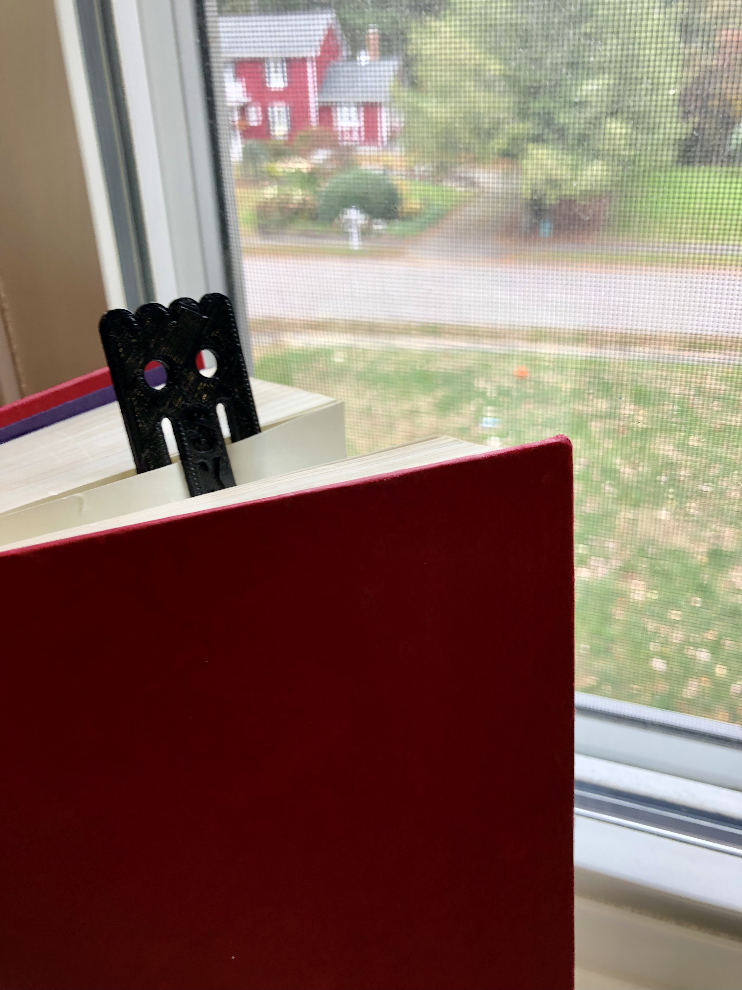
<p><strong>Summary:</strong></p><p>Are you looking for something that can help with simple household functions? This clip is exactly what you are looking for. It's a combination of a scary ghost-looking physique and clip function that can hold papers and close bags to your heart's content. You can use this clip everywhere, as its perfect size 3.1cm by 6.66cm makes it perfect to keep in your pocket and use. You can even customize it by engraving your own initials!! For this project, I worked in collaboration with Valerie Chung and you can find her page here. </p><p><strong>Project Goal:</strong></p><p>My partner and I were given the task of recreating the example ghost that was given to us using Solidworks. The goal was to have an Identical model with your partner. This was a challenge, and the way that we overcame it was to do each step together, making sure all of our measurements are exactly the same. To finish our project, we had to make sure our sketches were fully defined and we didn't have extra dimensions to keep our project as simple as possible. We also had to use the offset and mirror tool to demonstrate our understanding of those tools. </p><p><strong>Instructions:</strong></p><p> Make a center rectangle of the origin. </p><ol><li>Dimension the box to 3.1cm by 6.66cm.</li></ol><p><strong>Bottom Triangles</strong></p><ol><li>Make reference geometry for triangles on the bottom. <ol><li>start with a construction line 0.6cm up from the bottom of the constraint box and dimension it. </li><li>Then make construction lines for 1.033cm from the right edge of the constraint box, and then more construction lines 1.033cm apart from each other.</li><li>Identify the center of each 1.033cm segment (vertex of the triangles) with points at 0.516cm away from each 1.033cm mark.</li></ol></li><li>Connect the dots with lines, starting from the intersection of the 0.6cm line and the right edge of the constraint box, in a zigzag fashion until the left edge of the constraint box is reached.</li></ol><figure class="image image-style-align-center image_resized" style="width:32.34%;"><img src="https://lh3.googleusercontent.com/IhPy7jhJNLMsXWutAlR2dNmRjSLUCVHENgpqWIrWcX7PC1ysCv3EAmpx0FKbb9umfUFpgR1DTZQHRX2qI-c2A2dPNxvAY0NsHkBhmeq9AaPFSA2tg_i_u_o70UW0s_JlIDPY9cfLe4whd-xg2g-5LMxURUgh9K_Y-cmr1W_x9GEdDH7M78Z8XrbdVg"></figure><p><strong>Mouth</strong></p><ol><li>Make another reference line 1.8cm up from the bottom of the box</li><li>Make another reference line 0.95cm up from the bottom of the box. Identify the point where this line intersects with the vertical center line.</li><li>Make another reference line 4.13cm up from the bottom of the box.</li><li>Make vertical reference line 0.7cm from the right side of the constraint box (the line should be between the 4.13 and the 1.8 horizontal reference lines.</li><li>Connect the bottom of the the 0.7cm line to the point identified in Step 6.</li><li>Mirror the vertical and diagonal line across the centerline.</li><li>Reverse offset this U shaped series. Turn cap ends on and make the radius 0.175cm.</li><li>Dimension the width of the mouth to be 0.3 cm.</li></ol><figure class="image image-style-align-center image_resized" style="width:34.94%;"><img src="https://lh4.googleusercontent.com/7zJGR1cH3cUWiooRBy-EOZotPfAf4CjCzmVD6bFX76nnP_EOQJsju-NRXmsRNxl6y04a9worVhtLWHfRbnVlz5A4OuIhbBj1sdAxwI6kTsaFGszeTyHqJGL8fF9m4WvrxUV37Z0P8PN8mQcA2FntKfYgIVhFI53n0v9W95dQ60PppoRdYxf7wokQ5w"></figure><p><strong>Eyes</strong></p><ol><li>Make a horizontal reference line 4.85cm up from the bottom of the box. </li><li>Make another horizontal reference line 5.5cm up from the bottom of the box</li><li>Make a vertical reference line 0.6cm away from the right edge of the constraint box.</li><li>Make a vertical reference line 0.65cm away from the 0.6cm line made in Step 15.</li><li>Notice the rectangle made from the intersections of the reference lines.</li><li>Make a 3pt circle at the center of the rectangle and smart dimension it to have a diameter of 0.65 cm.</li><li>Mirror circle over the centerline to create the second eye.</li></ol><figure class="image image-style-align-center image_resized" style="width:53.2%;"><img src="https://lh4.googleusercontent.com/w_N7xwGuLOQBtFJyWvYKCvJ_LYW2W-EuApMWbrFMOrfik4Hs2zPvmy6usY3G65uRAMU6iC0Ts65I7Rom0g-Zi6aRZ0gJ0G2fpnHBCSmGeQJNAI5SrbRYiYvzfbmXLOwgGiMHEQ5kuidBWP7Sdx-sbzjcQYgZXJYfdbMGJs70fRwjUayMmPxk6_Ms7Q"></figure><p><strong>Top semi-circles</strong></p><ol><li>Make a horizontal reference line 6.25cm up from the bottom of the box. </li><li>Make a vertical reference line 0.775cm away from the right edge of the constraint box.</li><li>Make a vertical reference line 1.55cm away from the right edge of the constraint box.</li><li>Draw a semi-circle (flat edge on the 6.3cm line) with the endpoints on the right edge of the constraint box and the 0.8cm line. The top edge should be touching the top of the constraint box. The diameter of the semicircle should be 0.775, after smart dimensions.</li><li>Draw another semi-circle (flat edge on the 6.3 line) with the endpoints on the 1.6cm line and the 0.8 line. The top edge should be touching the top of the constraint box. The diameter should be 0.775, after smart dimensions.</li><li>Use a mirror tool to mirror over the centerline of the constraint box. There should be four semicircles at the top of the clip drawing.</li></ol><figure class="image image-style-align-center image_resized" style="width:63.57%;"><img src="https://lh3.googleusercontent.com/Md65pVGBritFHWZTqAna3OtDwhhe0ip4A8NF_bZvVpBTTdIhDOBZeI0N8O0eLKDZpDKr65V_XdolOTefsvciw9V7r67sNVRGe-GIQnDaHsgtSWECspj2ex0mdRuuOz721m7a1UrxM_V1rDKiefveOtoe3-VlF2tydK-zD3ba3PQF20_LK3OPrXH1GA"></figure><p><strong>Extruding and adding letters</strong></p><ol><li>Extrude the sketch using extruded boss/base tool.</li><li>Sketch two horizontal lines on the center flap of the clip.</li><li>Click on the lines and add text to it. Change the font to Impact and adjust positioning and size to your desire.</li><li>Then use the extruded cut tool to indent the letters.</li></ol><figure class="image image-style-align-center image_resized" style="width:19.97%;"><img src="https://lh4.googleusercontent.com/9jwsVyvKvf4Eu6MR2eISNDQp7WW3RLPLtx2Hjt9mr8iQHR2rnj9_ccorlja9W2eFG-c9AN5CSOT4F6Avqg9r5YO1b4w4B3GMjUJbkM-C21C-7xblD_9tQEk1qoLVb6OOXou2HcXRr5-lpZfFh-41K6Kl1Yn9pQ0b-bzLix9-VcqrUSrhfrEKzj0_LA"></figure><p>The first step of making these ghosts was to sketch them out on a piece of paper. We had to sketch them with 2x dimensions so that we could get a more appealing view of the ghost. Having it 2x bigger also helped our dimensions that we drew on the paper be more spread out and not crammed. However, the dimensions that we labeled on the paper were the dimensions of the actual ghost, not doubled(2x).To start our drawing, we made many reference points and measured using the centimeter side.</p><figure class="image image_resized image-style-align-center" style="width:30.97%;"><img src="https://lh4.googleusercontent.com/QC5StmCog7mqtNHuu0Hr8itOTu0u5wpGpPgAAUVe9nWGClCrGaSMA2_fX5uS7bXNbetN5wUyR_FhmyGPHMqwnvCkrH5HA5kToj1adIb8BkLo-9PadQvfIlxhdYxLX4iFi8l2ZD16p1NVPYOxHxHKeVNmP9m2v6mY1R6P2vZchSwwlpcETkSdt-jOGA"></figure><p>While measuring the ghost and recording measurements on paper, we ran into some issues. Measuring the curves and sharp ends of the ghost became very difficult. Finding the starting points of the curves was almost impossible due to the curve being morphed into the body of the clip, and not giving us a clear starting point. </p><figure class="image image_resized image-style-align-center" style="width:36.74%;"><img src="https://lh4.googleusercontent.com/lvJOuA8WH_4ppPiVp-F_eqPa5IRt87jJlj0-l8g5b1ZLaCd1JVs_-mDxjZ3PAbHhPu-_4Qw3sDEcEXDDIwpZndhSfzQzQJJZDfweUfGB1rJFKQELpkt7nb8Vkb74_YJ0uYN4c1Pc1WBGfWLju-l4qzQIkP4ZJmAbMePkN4AR2atKRUU9mtz1omlYdA"></figure><p>After completing our design on paper, we moved into Solidworks. In Solidworks, we began creating our reference geometry for our ghost. Also, there were some dimensions that changed when we moved into Solidworks. Our dimensions that we measured on paper were not adding up properly. Our top bumps measured to be 3.2 cm on paper, but the bottom triangles measured to be 3.3 cm. While measuring on the paper, these measurements weren’t seen as an issue due to the drawing making it look all equal. But when you are putting these measurements into Solidworks, the total length for the top and bottom has to be equal. When we first tried to enter the measurements that didn't add up, we were bombarded with multiple error messages telling us our issue. In this situation, we went back to measuring and came back with a more accurate consensus measurement that added up on both the top and bottom sides of the ghost. </p><figure class="image image_resized image-style-align-center" style="width:46.92%;"><img src="https://lh6.googleusercontent.com/AyISe67o0zYsaWAL2URSdTpj6vgRah3-QMBLuYNTrbqxJQAP8WBiopl_u-2peium4XPjO_Za9K3G2UVdOriBFSWHsrbDAoIPIm9YMeCTy_R8GF1x8WSkCAajQ9wseueOEsKEj6gYGvV1PnClje_dKRjEEjxqCvditmoqVl3-f13uv-IIm9V0WeIlBg"></figure><p>While making the mouth, the original plan was to draw half of it and mirror it. After rethinking this process, we came out with two possible outcomes. Mirroring may cause problems in Solidworks and potentially cause the software to crash. The other thing that we came out with was that we could use the offset tool to accomplish the same thing we would have accomplished with the mirroring tool but more efficiently. With the offset tool we only had to draw and connect 4 lines while if we had used the mirror tool, it would have taken more time and effort to accomplish the same task.</p><figure class="image image_resized" style="width:12.5%;"><img src="https://media.printables.com/media/prints/301328/rich_content/efc458f5-9973-45c2-96fd-7e49228216c4/screen-shot-2022-10-23-at-83958-pm.png#%7B%22uuid%22%3A%2212459da9-1c5c-4879-9cdd-31d14b333745%22%2C%22w%22%3A226%2C%22h%22%3A730%7D"></figure><p>While making the top bumps, we brought the offset tool into consideration. We started to think about the idea that we could create the semi-circles using the cap ends feature on the offset tool. We would then delete every line except for the semicircles created by the cap end part of the offset tool. We tried to implement this idea, and we ran into some issues. The arcs that were created were not defined. We were having a lot of trouble trying to define them and we ran into a lot of errors. Also, the mirror of the semicircles was not functioning properly. It was also breaking the design, and giving us a lot of error messages. After all the trial and error, we decided that we would go back to the original idea of just drawing out the semicircles. </p><figure class="image image_resized" style="width:11.68%;"><img src="https://media.printables.com/media/prints/301328/rich_content/a57670e3-b320-4528-9f74-e51cf44b4c68/screen-shot-2022-10-23-at-84010-pm.png#%7B%22uuid%22%3A%22a6e6a0e3-ce83-4c8d-acd6-df1eb544adce%22%2C%22w%22%3A156%2C%22h%22%3A566%7D"></figure><p>The final step in our project was to compare our ghost in Solidworks to the original ghost to make sure that our location of the mouth and eyes were in the right place. When we lined up the example ghost to the computer, we realized that we had to make our design smaller. We were only using our eyes to compare our sketches to the model so most of our changes were for aesthetics. </p><p> <img class="image_resized" style="width:21.81%;" src="https://media.printables.com/media/prints/301328/rich_content/69831a44-d474-48de-8533-7145ab06f586/soham_screenshots.png#%7B%22uuid%22%3A%222321035a-a477-4ca4-a3fc-567f36890125%22%2C%22w%22%3A825%2C%22h%22%3A1594%7D"><img class="image_resized" style="width:20.09%;" src="https://media.printables.com/media/prints/301328/rich_content/b564edcb-e1ae-4135-bb8f-3b0452f5bf51/screen-shot-2022-10-23-at-84248-pm.png#%7B%22uuid%22%3A%220c83d863-ff38-4e96-a109-aa3b5c6be58b%22%2C%22w%22%3A598%2C%22h%22%3A1230%7D"><br> </p>
With this file you will be able to print Ghost Clip with your 3D printer. Click on the button and save the file on your computer to work, edit or customize your design. You can also find more 3D designs for printers on Ghost Clip.