Ghost Clip
prusaprinters
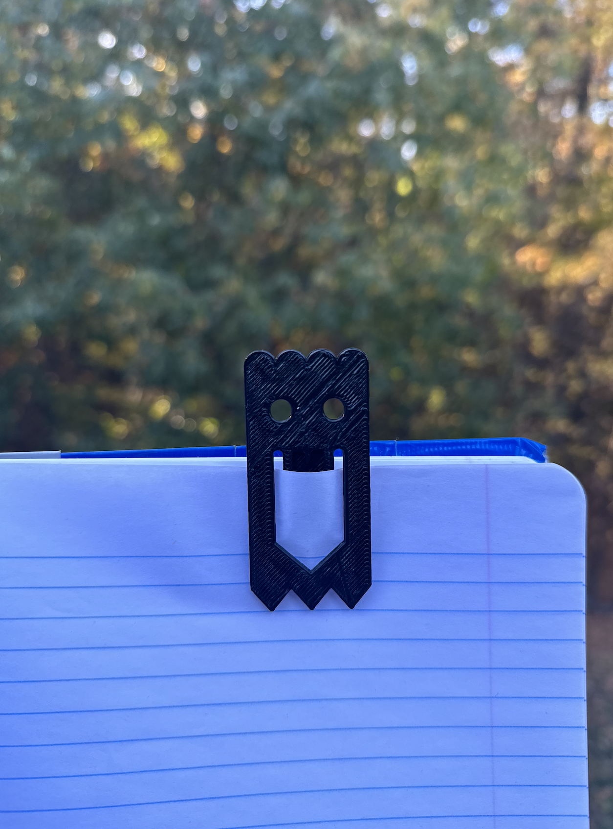
<p>(Continued Summary) …that you could have as a stand-alone piece or utilize as some sort of paper clip. The clip is relatively small and easy to carry around when you either need a fun pick-me-up fidget toy or when you need to keep a stack of papers together. The dimensions of the clip are 3cm_X_6.5cm. Initially, we had an example model to measure out and transcribe 2X scale onto a paper and then transferred that drawing into Solidworks where we sketched and created the 2D version of the model. Once sketched and identical to the model as well as our partners we then extruded the model to 3D and added our initials. </p><p>My partner’s Ghost Clip can be found under the username of JoJo.</p><p><br>Construction Instructions: </p><p>With a partner, you will recreate your ghost clip using Solidworks from a model example provided in class. You and your partner MUST have identical files that you create by collaborating on each step, one at a time.</p><p> </p><p>How it was made in Solidworks:</p><p>1.Constraint Box </p><ol><li>Start with the perpendicular edge at the origin and create a rectangle off of that point. </li><li>Create two constraint boxes for both the triangles with your dimensions from the bottom and half circles dimensioned from the top.</li><li>Make two construction lines in the center horizontally and vertically.</li><li>Mark all these boxes with correct dimensions.</li></ol><p>2.Create a standard box for the main construction of the ghost</p><p>3. Circular arcs</p><ol><li>Create 4 arcs in the top of the constraint boxes between the top and closest bottom constraint. Set them all equal to each other.</li><li>Flat end of the arc is facing towards the center while the ending arc is facing outwards.</li></ol><p>4.Circular eyes</p><ol><li>Measure out from the left side and create a construction line for the horizontal axis the eyes will be on. Find your dimensions and then plot your eye point.</li><li>Make the diameter of the circle as shown on the paper and then mirror the circle onto the other side</li></ol><p>5.Triangles</p><ol><li>Create 7 constraint points switching from bottom to top separated by your specific dimensions. </li><li>Add diagonal lines between these points. </li></ol><p>6. Mouth</p><ol><li>From the midpoint at the bottom measure up from the bottom of the mouth's midpoint repeat this again for the top of the mouth's midpoint.</li><li>dimensioned from the top create a constraint box for the top of the smile. For the closest side add your dimensions between the two lines. Then add your dimensions down on each line.</li><li>From the top of the horizontal smile on the closest side measure out your dimensions as well as the farther side.</li></ol><p>7.Mirroring</p><ol><li>Make sure the line dimensions are matched up with the design shown above or similar to scale.</li><li>Singularly select every line besides the construction lines from the right side after completion. </li><li>Once selected click the mirror entities button at the top of the screen.</li><li>The design should now be perfectly mirrored and identical</li></ol><p>8.Extruding</p><ol><li>When all is mirrored you now are able to extrude by selecting the boss extrude button and tweak it to your desired width. </li></ol><p>9.Initials (optional)</p><ol><li>Select extruded cut</li><li>Select the plane you want the initials on</li><li>When selected on the plane you want to make a new sketch </li><li>Find the text button</li><li>Type in desired text</li><li>And when back on the extruded cut you will select the sketch with the letters and extrude cut into the object.</li></ol><p> </p><p>The choices made through the design: </p><ul><li>To ensure that my partner and I’s project would be identical throughout, we split up the planning steps. </li><li>The first step was to observe the model and figure out what key points we will need to sketch constraints for and anchor points.</li><li><img class="image_resized" style="width:20.32%;" src="https://lh6.googleusercontent.com/e8yR6F6lsv70EzK34nWpLmef59Ab5nVMnyFvb-foXxXcwATiBykIUOedcu2NSs8HYDO6Pk8qe7lUqaSRru5rV_Bl3dNH-YRpq_Q_MsCA75XV-FA5oLO4SsnOMjzSV4VvwJqJrDRCzWquJ2WEjoCggEJ7jIJdgtK8lhkmLrnsKRFXmfJ4oEGUCJwILw"></li><li>After discussing it we sketched out a physical example of the example paper clip model onto a piece of paper. </li><li>We measured out the construction dimensions which would be the perimeter. After the construction dimensions were laid out we made anchor points where each line came to an intersection. We also made an anchor point roughly in the middle of the eyes. (dark black lines)</li><li><img class="image_resized" style="width:51.31%;" src="https://media.printables.com/media/prints/301769/rich_content/f61518a6-f15b-4d02-a659-88d07e9ed980/screen-shot-2022-10-23-at-112718-pm.png#%7B%22uuid%22%3A%22c4bc4810-0f6a-4d61-b068-cad715137d6b%22%2C%22w%22%3A814%2C%22h%22%3A1154%7D"></li><li>When drawing the sketch onto the paper keep the identical measurements but scale them to 2 times the size and transcribe onto the paper. </li><li>When scaled keep the same measurements as the original model. We originally created a smaller sketch alongside but it was unneeded and solely for an idea of what the original size was. Keeping the scale of 2X would be beneficial later down the road as it is easier to read and when needed easier to change and adjust.</li><li><img class="image_resized" style="width:64.64%;" src="https://media.printables.com/media/prints/301769/rich_content/aea752a3-e848-460c-a152-3610f31b77c3/screen-shot-2022-10-23-at-113228-pm.png#%7B%22uuid%22%3A%22e48edfd3-c5e0-4b60-9f24-008310641d96%22%2C%22w%22%3A1286%2C%22h%22%3A1166%7D"></li><li>After the drawing was complete we moved onto the computer where we booted up Solidworks and would then sketch the ghost initially on a 2D plane.</li><li>We mapped out the rectangular constraint box with the measurements of 3cm by 6.5cm and then a construction line down the center of the rectangle. To save time we focused on only the right side to create our design because we will easily mirror it on the left side farther down the line.</li><li>Following this, we then focused on making the semi-circles at the top of our ghost. In doing this based on our paper sketch we created a construction line that was initially 0.4cm away from the top constraint box line. We then placed the model ghost onto the screen and found that the circles were too far down so we decided to raise only the construction line by 0.05 to give us a height from the top of 0.35cm as shown below. We changed this to better fit the example model aesthetically to match the measurements and functionally. We then drew arches that were each 0.75cm in diameter. </li><li><img src="https://media.printables.com/media/prints/301769/rich_content/41d5fd97-8fdb-4533-ad4b-3fc386cc4b62/screen-shot-2022-10-23-at-113038-pm.png#%7B%22uuid%22%3A%22b91aad16-4ef2-4d02-8293-802e8bfb0ce7%22%2C%22w%22%3A776%2C%22h%22%3A316%7D"></li><li>After the arches were complete and dimensioned off we moved on to the triangles at the bottom of the model. Using our paper as a guideline we made a construction line for all the triangle's bases to meet at 0.6cm and had their anchor points every 0.5cm. Here our paper sketch was accurate so it was an easy transition onto Solidworks.</li><li><img class="image_resized" style="width:67.08%;" src="https://media.printables.com/media/prints/301769/rich_content/59d5e908-2ca6-4cf1-8bfa-266a1ed0e4ac/screen-shot-2022-10-23-at-113028-pm.png#%7B%22uuid%22%3A%2229178381-afcd-496c-9eae-f46e5b1a0c55%22%2C%22w%22%3A706%2C%22h%22%3A380%7D"></li><li>Now in terms of the eyes based on our interpretation, we made a horizontal construction line that would pass through the midpoint of the circle 1.45cm down from the upper constraint line. Next, we dimensioned the circle's midpoint 0.85cm away from the edge constraint line and gave it a radius of 0.6cm. When we lined up our ghost clip example model to the screen it looked accurate.</li><li><img src="https://media.printables.com/media/prints/301769/rich_content/5067f218-61d5-4d64-9179-bd761647507b/screen-shot-2022-10-23-at-113019-pm.png#%7B%22uuid%22%3A%22262f52da-0a20-4970-bce5-1553fb0014e3%22%2C%22w%22%3A294%2C%22h%22%3A238%7D"></li><li>Now it was time to make the smile, which would be the most tedious part. We once again started with anchor points and first put down the bottom of the smiles points that lay on the centerline. We measured up the bottom point at 0.9cm and the point above it at 1.2cm leaving a gap of 0.3 in between. After we plotted where vertical smile lines ended with the outside line ending at 1.7cm and the inside being 1.88cm above the bottom constraint line. </li><li><img src="https://media.printables.com/media/prints/301769/rich_content/fe8e322f-3d3e-417c-91fc-8159a1bb3b40/screen-shot-2022-10-23-at-113012-pm.png#%7B%22uuid%22%3A%22b0883732-c83e-4631-88d9-d82ba8bec148%22%2C%22w%22%3A568%2C%22h%22%3A176%7D"></li><li>We then measured where the arc of the smile ended and got a measurement of 3.95cm above the constraint line. With those two points and an arc at the top, we were able to offset with our measurement of 0.3. </li><li><img class="image_resized" style="width:92.68%;" src="https://media.printables.com/media/prints/301769/rich_content/7e59001a-cef0-4677-ad68-e5ba306fc91a/screen-shot-2022-10-23-at-113005-pm.png#%7B%22uuid%22%3A%228660d79b-660e-471f-a630-74a303337a6d%22%2C%22w%22%3A616%2C%22h%22%3A324%7D"></li><li>Now came the part where my partner and I had to critically think. As we offsetted with capped ends they extended beyond the centerline and we were not sure what to do. We then remembered that we could delete line portions up to a certain intersecting line and that's exactly what we did for every point that extended onto the left side of the figure.</li><li>We then selected every nonconstruction line and mirrored it over the construction center line with no issues.</li><li> <img class="image_resized" style="width:48.66%;" src="https://media.printables.com/media/prints/301769/rich_content/63aa19fd-37fe-400e-8fb9-e179602dc4ac/screen-shot-2022-10-23-at-112922-pm.png#%7B%22uuid%22%3A%22c0a45de3-6ca7-435b-8f7e-92e0003563d9%22%2C%22w%22%3A1106%2C%22h%22%3A760%7D"></li><li>The final 2D Ghost clip design in all of its glory.</li><li>The changes made through the project were to improve the outcome of the design to best fit the original model. These changes attributed to a better overall design through both functionality and aesthetics. </li><li><img src="https://lh3.googleusercontent.com/X9rGWHRik8gjVSGmHwP822pGP1JnthEuCcpvDHWz-cf-bwwZTNgg9qPUDgjzFs8eLaN3E7IwP0b9TooLGr6sUGIp0KZwKWAAQMQRsAXeamA1sdue5vSNG6HjHZm-bStG8IT5U3EZp9t-iyEtRnuH41_GebHxR_eF2IWWDDHkluu8p4l0bxGw_Z_vrQ"></li></ul>
With this file you will be able to print Ghost Clip with your 3D printer. Click on the button and save the file on your computer to work, edit or customize your design. You can also find more 3D designs for printers on Ghost Clip.