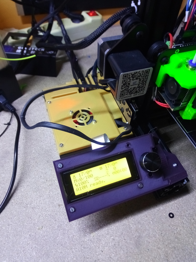
geeetech a10m side box and cable management
thingiverse
I'm glad to have things neatly organized on my desk. It makes troubleshooting and maintenance work much easier. This firmware has been tested on an A10 machine, but it's likely to work just as well on an A10M. To get started, you'll need to: - Print a new Y endstop mount because the cables are too short for this printer. - Create an extension power cord so the PSU can be placed in its original position. I've been using mine on the side of the back of my printer, and I'm planning to do a dual rod mod. To assemble everything, you'll need: - 12-15mm M3 bolts for the cover box. - 7 M4 or M5 t-nuts. - 7 M4 or M5 bolts (10mm) for the t-nuts. - 2 M5 bolts for the back box. You can use the original one, and you'll need two nuts to insert into the printed 2020 slot. - 2 M3 bolts (15mm) for the Y endstop. - 4 M3 bolts and nuts (15-20mm) for the LCD part. - Zip ties for cable management in the back. Take a look at the image to see where you should insert the cables. My plan is to build a Raspberry Pi box under the LCD screen and adapt the cables to fit it.
With this file you will be able to print geeetech a10m side box and cable management with your 3D printer. Click on the button and save the file on your computer to work, edit or customize your design. You can also find more 3D designs for printers on geeetech a10m side box and cable management .
