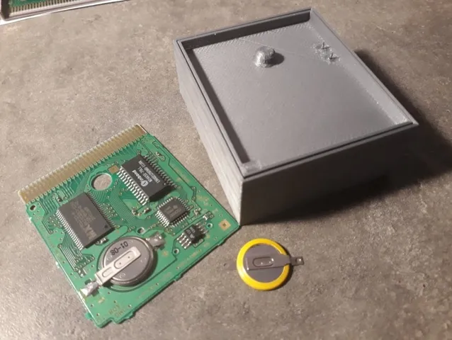
GB Cartridge Probe Holder for Battery replacement
prusaprinters
An overkilled Game-Boy Cartridge holder to keep SRAM powered during a battery replacement and thus keeping your precious saves. Taking use of Test-Point at the back of cartridge PCB. TP1 : RawPower -> Direct connection to SRAM's +VCC TP2 : +3V pin of Battery/GB power manager µC (ref 134A or 26A) (TP2 is connected to TP3 via 10k Ohm resistor R1) TP3: +3V Battery TP4: GND !!! WARNING: On first picture pogo pin is placed on wrong test-point. Supply +3V on TP3 will keep you SRAM powered but will damaged your already nearly depleted coin cell !!! Minimal circuit for correct use is to supply +3V between TP1 (+VCC) and TP4 (GND), which could be achieve by soldering a CR1616 between 2 pogo. A proper circuit would use a battery holder (there is enough room for 2 AA cell for exemple) and eventually use feedback from TP2 to shine a led to inform of correct pogo-pin contact. Designed for 1.5mm diam pogo-pin, but it would accept any size with a little drill help. Future improvement would be the add of something to apply pressure to the pcb to maintain it on the pogo. Ideally a clamp with a spring for easy remove. Circuit schematics are available here thanks to Jeff Frohwein's work : http://www.devrs.com/gb/files/hardware.html http://www.devrs.com/gb/files/mbc1.gif http://www.devrs.com/gb/files/134a.gif Print instructionsCategory: Electronics Summary An overkilled Game-Boy Cartridge holder to keep SRAM powered during a battery replacement and thus keeping your precious saves. Taking use of Test-Point at the back of cartridge PCB. TP1 : RawPower -> Direct connection to SRAM's +VCC TP2 : +3V pin of Battery/GB power manager µC (ref 134A or 26A) (TP2 is connected to TP3 via 10k Ohm resistor R1) TP3: +3V Battery TP4: GND !!! WARNING: On first picture pogo pin is placed on wrong test-point. Supply +3V on TP3 will keep you SRAM powered but will damaged your already nearly depleted coin cell !!! Minimal circuit for correct use is to supply +3V between TP1 (+VCC) and TP4 (GND), which could be achieve by soldering a CR1616 between 2 pogo. A proper circuit would use a battery holder (there is enough room for 2 AA cell for exemple) and eventually use feedback from TP2 to shine a led to inform of correct pogo-pin contact. Designed for 1.5mm diam pogo-pin, but it would accept any size with a little drill help. Future improvement would be the add of something to apply pressure to the pcb to maintain it on the pogo. Ideally a clamp with a spring for easy remove. Circuit schematics are available here thanks to Jeff Frohwein's work : http://www.devrs.com/gb/files/hardware.html http://www.devrs.com/gb/files/mbc1.gif http://www.devrs.com/gb/files/134a.gif Print Settings Printer: i3 chinese clone Rafts: No</div>Supports: No Resolution: 0.25</div>Infill: 10% Filament: BasicFill PLA Sylver Notes: Depending of your printer a brim of 2mm might be a plus to avoid any wrapping.
With this file you will be able to print GB Cartridge Probe Holder for Battery replacement with your 3D printer. Click on the button and save the file on your computer to work, edit or customize your design. You can also find more 3D designs for printers on GB Cartridge Probe Holder for Battery replacement.
