Games / Robot Controller
prusaprinters
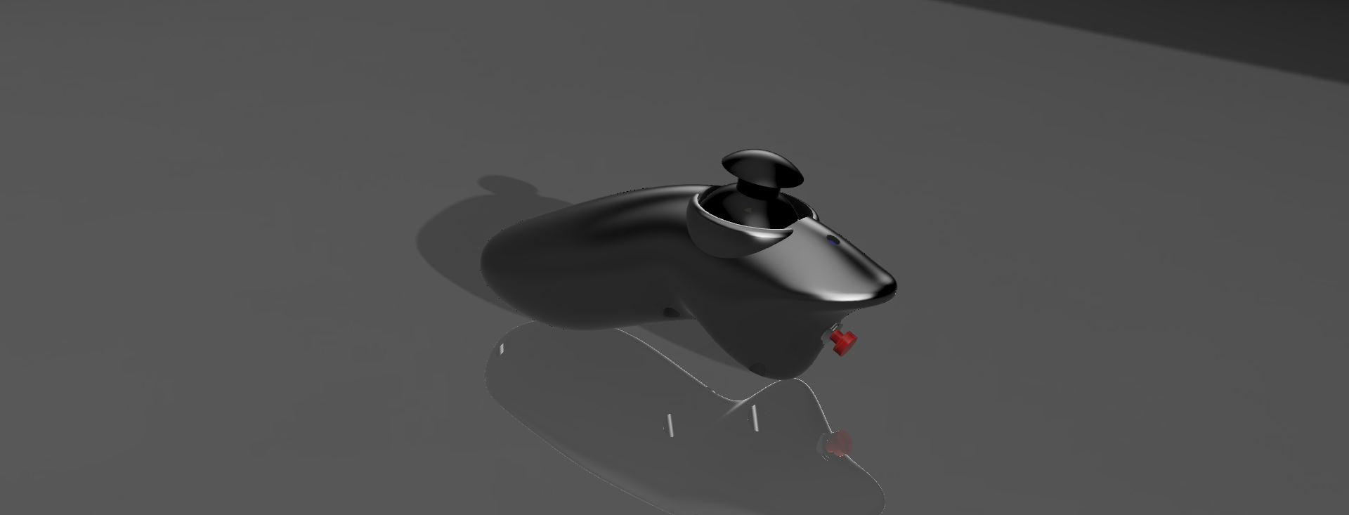
<p>I needed a controller for a robot project. it works with an arduino pro mini inside which streams the readings from the joystick, buttons and accellorometer to your main project via UART on a 4 core cable. (I used an old usb cable with the plugs cutt off.) you can also stream data back to the controller to change the neopixle's colour.</p><p>I originally printed this at 0.2mm layer heights in PLA, but the edges do take quite a bit of cleen up. with support turned on. each half was orientated so that the outside portion pointed up on the build plate.</p><p><strong>Parts:</strong></p><ul><li>The Joystick was a PS4 style joystick for arduino from ebay.</li><li>I used a pannel mount button for the front.</li><li>A 3.3v arduino pro mini. I chose to use a 3.3v version because the accellorometer runs off 3.3v rather than having to work with two different voltages and more regulators and level shifters. </li><li>An ADXL345 I2C accellorometer module.</li><li>WS2812B (Neopixle) smd LED + a 470 ohm resistor</li><li>six M2 10mm socket cap self tapping screws</li><li>some small screws for securing the ADXL345</li><li>hot glue</li><li>some perfboard</li><li>hookup wire</li><li>old USB cable</li><li>(optional) 5 way and 3 way JST connectors to make it easier to seporate the two halfs</li></ul><p> </p><p><strong>Preparing components</strong></p><p>On a short piece of perfboard solder on the WS2812B led and add wires for Vcc, GND and data in a 470ohm resistor needs to be connected in series to the data in pin. the data pin connects to D2 pin on the arduino.</p><p>Solder wires to each of the modules and buttons. </p><p>The arduino going to eventually be connected to a piece of perf board I started by adding headder pins but not the arduino at this stage. I then soldered wires for each of the modules to this erf board then added he arduino afterwards.</p><p>on the ADXL345 module if you are using an Adafruit module or clone levelshifting is built on board so connect Gnd to arduino Gnd, Arduino V+ to either 3.3v or 5v depending on what module you are using, SDA to arduino SDA (A4), SCL to arduino SCL (A5) (https://learn.adafruit.com/adxl345-digital-accelerometer/assembly-and-wiring) </p><p>For a sparkfun ADXL345 module or clone (Which is what I had) connect Gnd to arduino Gnd, Arduino V+ to 3.3v, SDA to arduino SDA (A4), SCL to arduino SCL (A5) CS to 3.3v and SDO to Gnd. (https://learn.sparkfun.com/tutorials/adxl345-hookup-guide/all#assembly)</p><p>I added the interrupt pin from the ADXL345 to D5 and D6 but I did not use then in the arduino sketch</p><p>The front button connects to ground and D3.</p><p>On the joystick solder wires to connect gnd to gnd, Vcc to 3.3v, X output to A0 on the arduino, Y output to A1 on the arduino, the button pin to D3. </p><p>The old USB cable I cut the plugs off and soldered the black wire to Gnd, the res wire to RAW then the white wire to TX and the green wire to RX. </p><p>There s a row of holes on the end of the arduino pro mini for programming via a FTDI programmer. I kept these holes clear for programming.</p><p> </p><p>The RAW pin feeds the onboard voltage regulator on the pro mini so the other end should work with either 5v or 3.3v micro controllers just level shift the TX signal from the hoast controller.</p><p> </p><p><strong>The Code</strong></p><p>There are two arduino sketches “Receaver_v1” & “Single_controller_V2” </p><p>The receaver_V1 was written for an Arduino Mega with more than one UARTs </p><p> </p><p>Single_controller_V2 is for the controller </p><p>Most of the SparkFun ADXL345 Library has been added but not used it's there just incase it's needed for future modications.</p><p>The button pin and the joystick button pin use a INPUT_PULLUP so when a normal (Push To Make) the pin goes low when pushed. For the front button I used a Push To Break switch so the logic needs inverting. </p><pre><code class="language-plaintext">//button_State = !b; // for use with PTM buttons button_State = b;// for use with PBM buttons</code></pre><pre><code class="language-plaintext">Joy_Button_State = !a; // for use with PTM buttons //Joy_Button_State = a;// for use with PBM buttons</code></pre><p>comment / uncomment as appropiate.</p><p> </p><p>On the hoast controller add some variables to store the incomming data.</p><pre><code class="language-plaintext">int Joy_X = 513; int Joy_Y = 512; bool Button_State = false; bool Joy_Button_State = false; int Acc_X = 0; int Acc_Y = 0; int Acc_Z = 0;</code></pre><p>In the main loop the hoast looks for the start of the data string by looking for '<' before initiating pareing data this is to avoid parsing data partway through the string.</p><pre><code class="language-plaintext">if (Serial.read() == '<')</code></pre><pre><code class="language-plaintext"> Joy_X = Serial.parseInt(); Joy_Y = Serial.parseInt(); Button_State = Serial.parseInt(); Joy_Button_State = Serial.parseInt(); Acc_X = Serial.parseInt(); Acc_Y = Serial.parseInt(); Acc_Z = Serial.parseInt();</code></pre><p>Stores the data for use elsewhere.</p><p>You can send colours to the LED on the controller by sending a string with three intergers one for each red, green and blue each seporated by a comma. Each interger should be between 0 and 255.</p><pre><code class="language-plaintext">Serial.print ("255 , 128 , 0"); Serial.print ('\n');</code></pre><p>It is inportant to add the new line “Serial.print ('\n');” rather than Serial.prinln the controller sketch sends data to the neopixle once it has receaved the ‘\n’ .</p><p><strong>Putting it together</strong></p><p>The screws hold the joystick in place so for the top half hot glue the LED in place.</p><p>The front button screws in place if you wish add the nut for extra security. </p><p>Screw or glue the accellorometer in place. the arduino pro mini on the perfboard slides in place with the UART wire through the hole. a dot of hot glue can hold the wire and the arduino in place. </p><p>Screw both halfs together using the six M2 x 10mm self tappong screws.</p>
With this file you will be able to print Games / Robot Controller with your 3D printer. Click on the button and save the file on your computer to work, edit or customize your design. You can also find more 3D designs for printers on Games / Robot Controller.