Free-piston Stirling engine
thingiverse
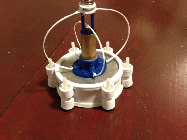
This is a custom-built Stirling engine designed to minimize metalworking requirements. To build this engine, you only need to cut two 3-inch aluminum disks and drill a central hole in one, then attach 4 pieces of tubing to 3D printed parts using glue. This design achieves a nearly fully 3D printed engine with minimal machining necessary. The piston, cylinder, displacer gland, and rod are made from brass tubing available at hobby stores (sizes used: 21/32", 5/8", 1/4", 7/32"). The rest of the parts are 3D printed using a Type A Machines 3D printer. The blue parts are PLA, while the white parts are PET+ purchased from MadeSolid. PET was chosen for its high-temperature resistance on the hot plate, though ABS might have been a better choice due to printing fumes. However, the engine's springs are its limiting factor. Any misalignment while running causes the displacer rod to rub against its housing, throwing off timing and slowing or stopping the engine. I also created an attachment that holds a coil of wire but found it insufficient for lighting an LED, with 800 turns being too few. To demonstrate the engine's efficiency, boiling water was placed in a thermos above ice on top of the engine during testing. You can view this process in the attached video: https://www.youtube.com/watch?v=Dxu6yYSwVnk Here are the print settings used: * Printer Brand: Type A Machines * Printer Model: 2014 Series 1 * Rafts: No * Supports: Yes * Resolution: 0.2mm * Infill: 20% * Notes: Print springs flat with supports. The displacer chamber and cylinder holder o-ring gaps were suitable for my printer, but I can adjust the gap if requested (sealing occurs on side walls). Some parts may need to be rotated during printing. Post-printing, materials are required: * Aluminum disks with a central 11/16" hole in one * Brass tubing in sizes 21/32", 5/8", 1/4", and 7/32" * 1" ID o-ring and 2 3/4" ID o-rings, both 1/16" thick * Small pieces of foam for regenerator slots and styrofoam for the displacer (1/4" thick) * Six 10-32 screws (1.5") and nuts * Optional: Disk magnets 1/8" thick, 1/2" wide, and thin magnet wire Refer to the attached video for running and assembly instructions. Custom Section: When building this engine, you will need to drill a centered 11/16" hole with small ears at 180 degrees to each other in one aluminum plate (to hold the bottom of the cylinder holder when the top is screwed on). Additionally, glue in the piston insert, piston cylinder, and styrofoam to the displacer.stl holder. The springs may require slight bending to achieve the right amount of "springiness" and height.
With this file you will be able to print Free-piston Stirling engine with your 3D printer. Click on the button and save the file on your computer to work, edit or customize your design. You can also find more 3D designs for printers on Free-piston Stirling engine.