FPV monitor & battery box
prusaprinters
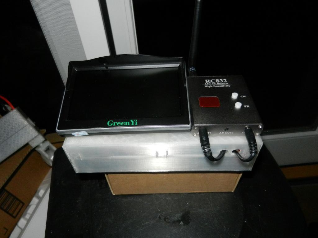
<p>The objective was to make a container to organize & contain an FPV receiver, LCD monitor, switched battery, voltage converter and all associated cables for easy transport and use. Versions for 5" and 7" LCD displays were produced.</p> <p>Both versions make use of pairs of 10mm x 2mm round magnets to retain the lid/back of the container. The magnets are CA glued to mounting blocks which, in turn, are CA glued to the box framework and the back/lid.</p> <p>The magnets used were similar to these: https://www.amazon.com/gp/product/B08156543C</p> <p>The 5" LCD used was this one: https://www.amazon.com/gp/product/B072FNQQXV</p> <p>The 7" LDC used was this one: https://www.amazon.com/gp/product/B06X1BKZVC<br/> This display came with a bezel for "in-dash" installation. I built the box around it, recessing the display in the box required a deeper box than with the 5" box which used surface mounting.</p> <p>Both boxes make use of an XL-6019 circuit to boost 2S battery output to 13.5v for both the LCD and the FPV receiver's use. The circuit board I used was this one:<br/> https://www.amazon.com/gp/product/B082XQC2DS<br/> A small 2 part box was printed to house the circuit board.</p> <p>A simple 12v DC switch provides for on/off switching of battery input. I used switches like these: https://www.amazon.com/gp/product/B07T1JG6BD<br/> They include a pilot light, which is not necessary but was simple to implement.</p> <h3> Print Settings</h3> <p><strong>Printer Brand:</strong></p> <p>Creality</p> <p><p class="detail-setting printer"><strong>Printer: </strong> <div><p>Ender 3</p></div><strong>Rafts:</strong></p> <p>No</p> <p><p class="detail-setting supports"><strong>Supports: </strong> <div><p>Doesn't Matter</p></div><strong>Resolution:</strong></p> <p>0.28</p> <p><p class="detail-setting infill"><strong>Infill: </strong> <div><p>20%</p></div><br/> <strong>Filament:</strong><br/> [</p> <h3> N/A PLA+ or PLA pro ](http://www.amazon.com/s?url=search-alias&field-keywords=N%2FA+PLA%2B+or+PLA+pro&tag=thingiverse09-20) N/A <br/> <p class="detail-setting notes"><strong>Notes: </strong> </p><div><p>I printed fat & fast. You can probably improve wall finish printing slower & finer. Supports may be useful for the larger round opening. </p></div> Post-Printing</h3> <p><strong>Assembly</strong></p> <p><div><p>You may well need to clean out or enlarge holes to accommodate cable end plugs or switch. A step bit is useful for incremental enlargement. </p> I bundled cables so only the needed amount was available & secured the bundle with zip ties.</div></p> <p>Attachment of the RC832 receivers to the boxes was done by using double sided clear "servo tape". This makes a secure attachment but is readily removable without damage if desired.</p> <p>I used crimp on female spade connectors for the wire attachments to the switch. Inexpensive switches are often easily damaged by heat from soldering & the crimp connectors avoid that possibility. The crimped connectors should be attached to 1) a + wire from battery connector to center silver switch tab; 2) a + wire from the XL-6019 input to outside silver switch tab; 3) - wires from XL-6019 input & from battery connector to outside brass switch tab. Battery connectors should be appropriate for the 2S battery you use.</p> <p>XL-6019 output wires should get terminated appropriately to power receiver & monitor. You probably need two sets of +/- wires attached to the output terminals.</p> <p>Once the wires with connectors are attached to the XL-6019 circuit while in the printed housing and the output is adjusted to the desired voltage, a couple of dots of CA glue can be used to secure the top to the circuit housing.</p> <p>The magnetic attachments were assembled by first CA gluing the magnets into clips, a pair at a time. The easiest way I found to keep things indexed was as follows:<br/> 1) glue a magnet into a clip, press in until fully seated & hold til the glue sets. 2) place that assembly magnet side down & put an empty clip on top so they are back to back. 3) apply glue to the empty clip & position a magnet - the magnet on the bottom will attract the proper face to the glue. 4) make sure to press the magnet in so it seats fully. Judicious application of pliers can help in fully seating the magnets. Repeat the process until you have six pairs.</p> <p>The assemblies get glued to the obvious locations on box frame & lid/bottom so that the magnets will meet face to face when the box is closed. Align carefully while gluing so they meet squarely for best results.</p> <p>I attached the 5" monitor to it's box by CA gluing the 5" attachment bracket to the removable box lid. 3mm screws & nuts connect the bracket to the link & the link to the monitor (after removing the tilt stand from the monitor back). You may want to screw the 3 pieces together prior to gluing so you can evaluate the preferred placement.</p> <p>The 7" monitor bezel snapped into place on the box face & the monitor snapped into place in the bezel.</p> <p>Clear servo tape was used to secure the receivers to their box. The 5" version has the receiver side by side with the monitor. The 7" version has the receiver on the left side of the box.</p> <h3> How I Designed This</h3> <p>This was done in tinkercad. The models are available if you want to do modifications:</p> <p>The 5" box : <a href="https://www.tinkercad.com/things/hue6b216P6e">https://www.tinkercad.com/things/hue6b216P6e</a></p> <p>The 7" box : <a href="https://www.tinkercad.com/things/kj4gfOxdeSQ">https://www.tinkercad.com/things/kj4gfOxdeSQ</a></p> </p></p></p> Category: R/C Vehicles
With this file you will be able to print FPV monitor & battery box with your 3D printer. Click on the button and save the file on your computer to work, edit or customize your design. You can also find more 3D designs for printers on FPV monitor & battery box.