Foot for bolt and square nut (SCAD)
prusaprinters
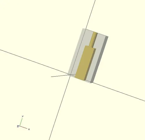
I needed to make a rail with #6 mounting hardware, but I started with this foot and it will be easy enough to adjust to a rail. This is for use as a PCB standoff, for example, when you want it to serve as a foot. Instructions Best to start with the SCAD unless you just happen to need the exact thing I did. Open foot-6.scad Adjust totalh, totalw, thick (height, width, thickness) The current settings are for #6 hardware, a square nut, and a 1/2" bolt hole (which does not mean you need a 1/2" bolt -- see below). Change as needed, save as STL, slice, print Say you have a 1/2" bolt hole and a 1/16" PCB. Then a 3/4" bolt will leave 3/16" for the nut to grab. Pick your bolt size appropriately. You may also need a very long bolt for installation (see below). If your printer is a little "tight" on holes, you may want to drill out the bolt hole. On mine, I can drive the bolt in and it "feels" threaded but it doesn't need a drill. However, the nut is square and not drillable. If it is tight (like mine is), push it in flush. Temporarily put a long bolt through the bolt hole and use it to pull the nut up through the hole. If it is too tight for that, you may have to hack the scad file to make a slightly bigger nut (nutsize) or take a file to the square hole (hard because the holes need to be concentric). You can also shove the nut down with something stiff but be careful not to tip it so it is on its side. Once you have the nut down to the bolt hole, remove the temporary bolt (if used) and put your PCB (or whatever) on top of the bolt hole. Pass the real bolt through the mounting hole on the PCB and into the bolt hole. Tighten. The modules for the bolthole and nuthole are there so you could make a strip of these with different offsets (my next step). Or just print them out and use them as feet. If you are an OpenSCAD guru this is probably not too exciting but I'm learning it and thought if not useful itself, might help someone else getting started. I was going to make a rail of these with multiple holes, but it is easier to print multiple feet. If you rotate to print vertically, make the square hole point up so your printer doesn't have to bridge the open hole. V2 just centers the hole unlike the first version where I was going to have a long rail with multiple holes. I will post a circular version derived from this shortly. Category: Electronics
With this file you will be able to print Foot for bolt and square nut (SCAD) with your 3D printer. Click on the button and save the file on your computer to work, edit or customize your design. You can also find more 3D designs for printers on Foot for bolt and square nut (SCAD).