FlukeEmu 9010A Emulator Case
prusaprinters
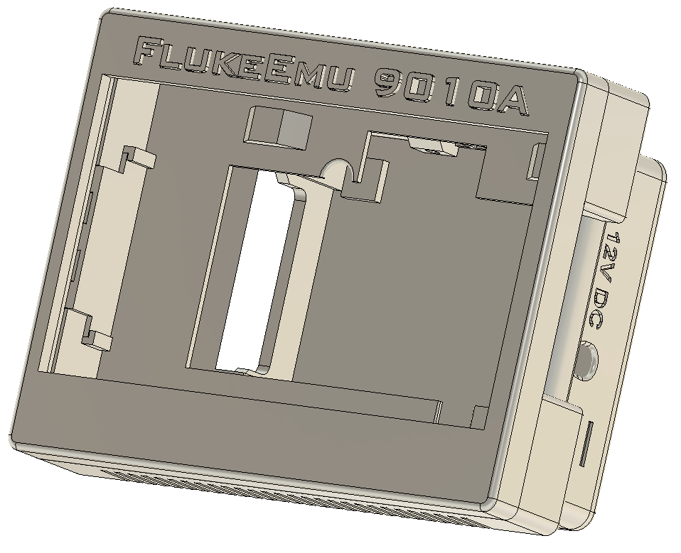
<p><strong>FlukeEmu 9010A Case</strong></p><p>The case was designed with specific parts as there are just too many variations of items out there.</p><p><br><strong>7" Touch Screen </strong><br>https://www.amazon.com/gp/product/B07L6WT77H/ref=ppx_yo_dt_b_search_asin_title?ie=UTF8&psc=1</p><p><strong>Micro SD Extension Cable:</strong><br>https://www.amazon.com/gp/product/B09KMZ56H9/ref=ppx_yo_dt_b_asin_title_o00_s00?ie=UTF8&psc=1</p><p>On the Touch Screens the quality control isn't the greatest, but the case tries to compensate for this. Of the 5 screens that were tested, 2 of them had larger bezel areas which required last minute tweaking.</p><p>On the SD Extension Cable, the cable is pretty stiff and makes installing a little challenging. Since the Pi doesn't have a locking SD slot the extension could come loose. In one instance we had to hot glue the extension to the Pi.</p><p>The case is designed to use Metal Inserts and either button head or flat head screws. </p><p>This was designed using the Pi3b+, but a Pi4 should work. The main difference is the HDMI connector is smaller and the Ethernet Port was moved to the opposite side of the USB connectors.</p><p>Access to the USB would require an extension cable, but I don't really see a need to access them. There is a cover that covers the access holes that the extension can be fed through.</p><p>I've also designed it to use a Small Fan. I don't know if it actually needs it, but it's supported if it does need it.<br>https://www.amazon.com/dp/B00NEMGCIA?psc=1&ref=ppx_yo2ov_dt_b_product_details</p><p>The bottom has 4 mounting holes, which I'm thinking of creating a base for it so it can be tilted. That will be a project for another day. The back also has a 75x75 VESA mounting pattern on it so you can mount it using that as well.</p><p><br><strong>Conventions used:</strong></p><ul><li>All holes that need a Metal Insert are 4.4mm (and 6mm for the VESA) in diameter and are not counter-sunk.<br> </li><li>All holes that are pass through are 3.2mm in diameter and are counter-sunk on the side that is where the screw is inserted.</li></ul><p><strong>Top</strong><br>Print with 4 Perimeters, 15% infill<br>Uses 4 Metal Inserts (3mm x 4mm)</p><p><strong>FlukeEmu Name Plate</strong><br>Print with 2 Perimeters, 15% infill<br>I also print with supports from build plate only.</p><p><i>Depending on the quality of the Touch Screen, this may or may not fit as well as it should. If you run into a problem with that, let me know and I can design an alternate version.</i></p><p><strong>Middle</strong><br>Print with 4 Perimeters, 15% infill, Supports for the 4 outside holes (Support Enforcers), edges don't need support.<br>Uses 4 Metal Inserts (3mm x 4mm)<br>Four 3mm x 25mm button head screws</p><p><strong>Bottom</strong><br>Print with 4 Perimeters, 15% infill<br>Uses 4 Metal Inserts (3mm x 4mm)<br>Four 3mm x 30mm button head screws</p><p><strong>Back Cover</strong><br>Print with 4 Perimeters, 15% infill, Supports for the 4 outside holes (Support Enforcers), edges don't need support.<br>Four 3mm x 8mm button head screws</p><p><strong>Fan</strong><br>Two 3mm x 14mm button head screws<br>Two Square Trapped Nuts or Metal Inserts. Trapped nuts are easier.</p><p><strong>Assembly:</strong></p><p>Assembly should be pretty straight forward. You'll want to put all the metal inserts in first. <br>Be careful when you do as they heat up very quickly and goes into the plastic like hot butter.<br>Metal Inserts go into the any hole that is 4.4mm and doesn't have a inset to hide the screws.</p><p>Install the Name Plate in the top. This is a tight fit and you want to be careful not to break anything installing it. </p><p> <br>It will take some force, but you can do it by hand. Make sure the back of the name plate is as flush with the Top as it can be or the LCD will not sit flat.</p><p>After the name plate is installed then the LCD fits in Top. It should sit flush to the edges. You'll want to line the holes up with the metal inserts. The orientation of the LCD is so that the speakers are sitting over the name plate.</p><p>After the LCD has been installed then the Middle is secured to Top with four 3mm x 25mm screws. <br><br>The orientation of the middle piece is so that the cut out is on the side of the LCD buttons. When installing, it's easier to put side closest to the buttons in first.</p><p>After the middle is secured then the Bottom is secured to Middle with four 3mm x 30mm. The orientation should be obvious.</p><p>Back Cover is secured to Bottom with four 3mm x 8mm screws.<br> </p><p><strong>Additional Notes:</strong><br>I normally print at 60C for the bed on PLA, but in this case I put it at 65C because I ran into some warping. With 65C I didn't see any warping. </p><p>I'm actually using PLA+ and not PLA when I print, but the files should work just fine for PLA as well.</p><p>The SD Card Stand can be a pain to install, so just be patient with that.</p><p> </p>
With this file you will be able to print FlukeEmu 9010A Emulator Case with your 3D printer. Click on the button and save the file on your computer to work, edit or customize your design. You can also find more 3D designs for printers on FlukeEmu 9010A Emulator Case.