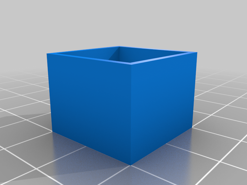
Flow Rate Calibration Cube
thingiverse
I have seen MANY people do this wrong. Printing 1 calibration cube is not enough! This test is the correct way to calibrate 3d printer flow rate. 1. use FreeCad to set the wall thickness of the calibration cube to 3x nozzle diameter (currently set to 1.2) and export to stl file 3. print the cube using both your normal settings and again in vase mode (spiralized outer contour in Cura) 4. measure the 4 sides of both cubes and input the data into the excel file along with the flow rate, and your acceptable error 5. iterate this with the new flow rate until the test passes then you will have the optimal flow rate I have entered the equations that I derived and tested into the excel spreadsheet, however here is a summary of how I got them: When printing there is the average thickness of the flow line and there is also some extra squish on the outermost wall than extends out beyond the average wall thickness (you see this as layer lines on the print). From this I derived 2 equations 1 for a cube with 1 wall line and another for a cube with multiple wall lines. so, with the 2 cubes there is a system of 2 equations and 2 variables (outer wall squish and flow thickness). From this the optimal flow rate can be calculated. The problem with the wrong method that many people use is that they print 1 cube and assume that the outer wall squish is 0, if this were true there would be no layer lines.
With this file you will be able to print Flow Rate Calibration Cube with your 3D printer. Click on the button and save the file on your computer to work, edit or customize your design. You can also find more 3D designs for printers on Flow Rate Calibration Cube.
