FlashForge 2016 LCD/SDCard/Keypad Interface Board Redesign
thingiverse
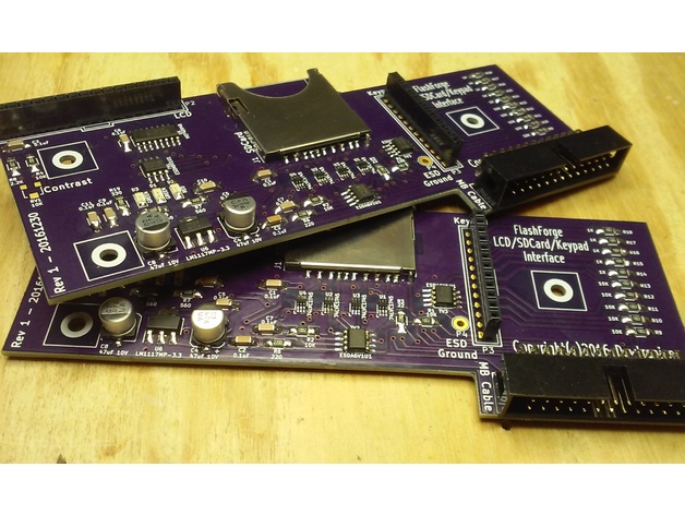
See this thing on GitHub: https://github.com/dewhisna/LCDInterface_FFCP.\nI'm fed up with having SDCard read problems on my FlashForge Creator Pro 2016 printers. I have three of those printers and all three experience the same issues. After studying and analyzing the schematics, I think the primary culprit is either ringing or a slight timing mismatch between the SCLK timebase and the unbuffered MISO data output from the SDCard. SDCards aren't designed to drive their data output down a 300mm ribbon cable.\nThen if you add in other issues like no bypass capacitors, limited decoupling capacitors, no ESD protection, long off-board 3.3V power runs, and misuse of a 74AHC125 as a voltage level translator, it's surprising that it works at all".\nI originally considered just building one of Gary's LCD ESD Protection boards for each of my printers, since the circuit in my FlashForge Creator Pro 2016 printers is nearly identical to the Replicator design. But, I decided that it wouldn't physically fit the printer very well.\nSince I had to make the boards anyway, I decided instead to completely redesign the main LCD Interface Board of the FlashForge -- which is the bottom board in the stack inside the plastic LCD panel. Boards can be ordered from OSHPark: https://www.oshpark.com/shared_projects/4YWmcdYh\nThe schematic, bill-of-materials, and PCB Gerber files have been posted here in the files section.\nUpdate (15-Jan-2017): I've received my boards from OSHPark and got them assembled. It came up and ran fine first time with no issues. So I've removed the "work in progress" flag.\nI did make one last-minute change in the parts I used from what is posted in the bill-of-materials. I decided to use a 0.001uF (1000pF) capacitor for C2 for the loading on the SDCard SCLK signal, instead of the 0.1uF. I decided on this change after running some numbers on the signal rise-time change that the added capacitor will create for the frequencies I believe the ATmega would most likely be using for the SDCard, based largely on calculation details in the textbook "High-Speed Digital Design: A Handbook of Black Magic".\nOtherwise, my boards were assembled as-per the diagram and bill-of-materials. And I did install the ferrite cable clamp that Gary suggested.\nSo far the new board has been working with no issues and with no read errors from the SDCard. Though the original FlashForge board worked OK sometimes too, so only time will confirm if I have truly solved the SDCard issues I previously had.\nIf I were to make any changes to the board on a future version, I would reduce the size of the 1206 SMD pads a bit, as I found them a bit annoying during hand-soldering. And, I would increase the annular ring size of the vias. The vias seem to be fine and are working well, but I always feel more comfortable being generous with design rules.\nFor reference, I posted a picture of my board along side the original (green) FlashForge board so you can compare them.\nUpdate (23-Jan-2018): It's now been a full year since I built these to go on my FlashForge printers. And I'm happy to report that with these boards, I've had zero read failures from the SDCard on any of my three printers, and they've logged many hundreds of hours of printing.\nI believe I can safely claim they have completely resolved my SDCard issues.
With this file you will be able to print FlashForge 2016 LCD/SDCard/Keypad Interface Board Redesign with your 3D printer. Click on the button and save the file on your computer to work, edit or customize your design. You can also find more 3D designs for printers on FlashForge 2016 LCD/SDCard/Keypad Interface Board Redesign.
