Finger Engine
prusaprinters
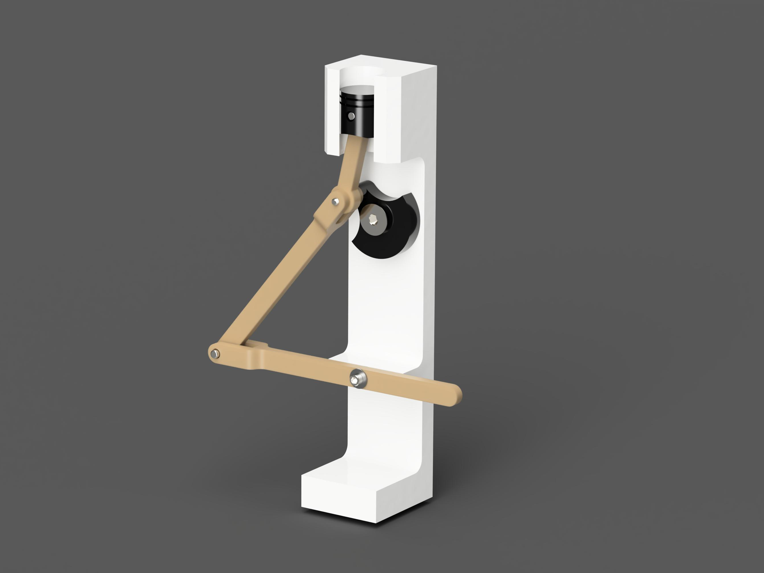
<figure class="image image_resized" style="width:31.96%;"><img src="https://media.printables.com/media/prints/294718/rich_content/f615eebc-5f35-42c4-a041-033c7d727de3/fingerenginer.gif#%7B%22uuid%22%3A%22efa6021d-411f-407a-afe7-7aa81ff5ca10%22%2C%22w%22%3A457%2C%22h%22%3A654%7D"></figure><p>Ever played with your grandma's treadle sewing machine? Pressing on the peddle allows the needle to move up and down and with better time and faster movement, the faster and longer it goes. This is the same concept, but a piston is moving through cylinder walls!</p><p><strong>BOM</strong></p><p>(1) 5x10x4mm - Bearing --> P/N: 7804K106<br>(1) 5 mm Shoulder Diameter, 4 mm Shoulder Length, M4 x 0.70 mm Thread --> P/N: 90318A760 <i>OR </i>90 Degree Countersink, M5 x 0.80 mm Thread, 14 mm Long --> P/N: 91294A211<br>(2) 7/64" Diameter, 1/2" Long - Dowel Pin --> P/N: 98381A021<br>(2) 2-56 Thread Size, 5/8" Long - Socket Head Cap Screw (SHCS) --> P/N: 92196A083<br>(2) 0.094" ID, 1/4" OD - Washer --> P/N: 90107A003</p><p><i>Note:</i> McMaster-Carr P/N's are for print reference, find your components at a local hardware store. Sorry for the confusion with both metric and standard parts, it's what I had laying around. <br> </p><p><strong>BUILD</strong></p><p>Start with a test print of the crankshaft and verify interference fit with the bearing.</p><p>Some minor sanding/filing will help the finger engine run smoothly. </p><p>Run screws through holes to cut threads and be sure to keep everything true! If screws are crooked, the finger engine will not run smoothly.</p><p><strong>Step 1:</strong> Insert the bearing in the crankshaft until the two surfaces are flush with each other. Install the 2-56 SHCS from the same side as the bearing, tighten until the threads are fully exiting the opposite side and the head has bottomed out. Set part off to the side for now.</p><p><strong>Step 2:</strong>Insert the roll pin through the piston hole with the small end of the connecting rod located within the slot of the piston. The roll pin should fit snuggly in the piston and loosely in the connecting rod. Verify that the piston can flop back and forth while wiggling the connecting rod. Good? Great, set component off to the side</p><p><strong>Step 3: </strong>Gather the linkages and insert the roll pin through the prongs horizontal linkage while the vertical linkage is concentric. Push the roll pin through and center the part (overhang is okay). Once again, the roll pin should be snuggly fitting on the horizontal linkage and loosely fitting in the vertical linkage. </p><p><strong>Step 4: </strong>Now grab your piston/connecting rod and insert between the prongs of the vertical linkage. Align the holes and push all components down onto the 2-56 screw coming out of the crankshaft. The fit should be loose, not allowing the threaded component to spin and push off the linkage/connecting rod. Now that you have both linkages, connecting rod, crankshaft, and piston all connected, it's time to install on the stand!</p><p> <strong>Step 5: </strong>Insert the piston within the cylinder walls (through the bottom) of the stand. Align the crankshaft bearing hole with the stands hole and install the 5mm screw. Tighten so the bearing can freely spin while the head is below the surface of the vertical linkage. Next, move the horizontal linkage into position and slide a washer behind and in front. Then install your 2-56 SHCS, tighten enough to keep location but loose enough that it can freely move.</p><p> Time to play with what you just created! Place the crankshaft at bottom dead center. Use one finger to hold the stand and your other to press down on the horizontal linkage. </p><p>Note: Adding magnets or some form of weight to the the horizontal/vertical linkage connecting point will help smooth the operation of the mechanism.</p><p> </p><p><strong>Edits</strong></p><p>10/16/2022: Changed 2-56 screw length, modified piston location within stand, new cover photo</p><p>10/17/2022: Photos with similar material color as 3d printed parts</p><p>10/21/2022: Updated renders</p><p>10/23/2022: Updated actual photos </p><p>11/01/2022: Note adding weight to horz/vert linkage connection point</p><p><strong>Future Updates</strong></p><p><strong> </strong>Fly Wheel</p>
With this file you will be able to print Finger Engine with your 3D printer. Click on the button and save the file on your computer to work, edit or customize your design. You can also find more 3D designs for printers on Finger Engine.