Feed Rod Bearing
grabcad
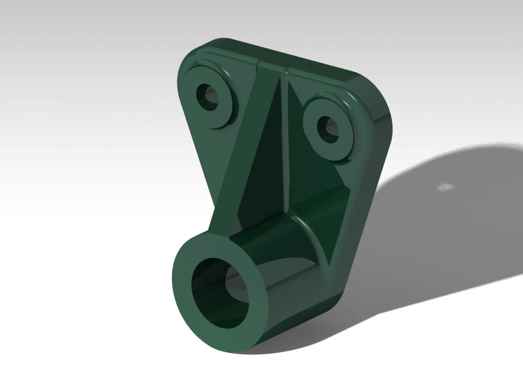
Designing a feed rod bearing from scratch utilizing CATIA V5 requires attention to detail and a solid understanding of the software's capabilities. The process begins with creating a new part, selecting the appropriate material properties, and defining the bearing's dimensions. To ensure accuracy, it is crucial to establish a clear understanding of the bearing's functionality and the forces acting upon it. This involves visualizing the movement of the feed rod, identifying areas of stress concentration, and determining the optimal bearing size. With this information in hand, users can confidently create the bearing's geometry using CATIA V5's parametric modeling tools. The software's intuitive interface allows designers to easily manipulate dimensions, angles, and other parameters, streamlining the design process. Once the bearing is created, it is essential to perform a thorough analysis of its static and dynamic characteristics. This includes simulating various loading conditions, such as pressure and vibration, to validate the bearing's performance under real-world scenarios. By leveraging CATIA V5's advanced simulation capabilities, designers can gain valuable insights into the bearing's behavior, making informed decisions about material selection, design optimization, and manufacturing processes. For those looking to expand their skills in CAD/CAM/CAE software, I invite you to subscribe to my YouTube Channel 'CAD CAM CAE Learning Solutions' for exclusive tutorials, design projects, and industry insights.
With this file you will be able to print Feed Rod Bearing with your 3D printer. Click on the button and save the file on your computer to work, edit or customize your design. You can also find more 3D designs for printers on Feed Rod Bearing.