Extrude Along Path
prusaprinters
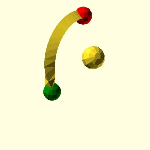
OpenSCAD script to generate the polyhedron that is formed by extruding a polygon along a specified path. List comprehensions allow the path and polygon points to be specified parametrically. Instructions This is a native OpenSCAD implementation of path extrusion. A polygon is specified as a set of points in 2D space, and a path is specified as a set of points in 3D space. The extrusion script copies the 2D origin-centred polygon along each of the points along the path, rotating each copy around the origin to face the next point on the path, and to be oriented in such a way that a unit vector perpendicular to the normal angle polygon matches up (as close as possible) with the same vector on the next copy. See the script 'path_extrude.scad' for the most recent version, implementing the above algorithm. The latest version is also available in a revision-controlled format from here. Updates from 2018 code: Essentially a code re-write from a blank state, but preserving the function signature Fixed up the polygon rotation / gimball lock issue by shifting a few negative signs around in the rotation function Tweening between two polygons with equal path lengths via 'exShape2' argument. This allows for a simple linear scaling as well (i.e. just make the second shape larger or smaller). Explicit scale and rotation options are available for simple tweaks of the polygons at each location Preparation: put path_extrude.scad into the same directory as your OpenSCAD code, and add "use ;" to the top of your OpenSCAD code. Syntax: module path_extrude(exPath, exShape, exShape2=[], exRots = [0], exScale = [1], merge=false) Creates an extruded path object by translating and rotating the shape described byexShape along the path described byexPath. Arguments: *exPath - 3D path through which shape will be extruded *exShape - 2D shape to extrude along the path *exShape2 [optional] - 2D shape to morph exShape into over the course of the extrusion *exRots [optional] - Additional rotation to be applied at each path point. If this is shorter than the length of the path, then it will be recycled. *exScale [optional] - Scale factor to be applied at each path point. If this is shorter than the length of the path, then it will be recycled. *merge - set to true if the extruded path should be closed between the end and start point (i.e. a closed tube with no end covers) Constraints: exPath should be a vector of 3D vectors of at least length 3 exShape should be a vector of 2D vectors of at least length 3 exShape should be a single closed polygon exShape2 should be a single closed polygon exShape2 should have the same number of points as exShape exRots should be a vector of at least length 1 exScale should be a vector of at least length 1 OpenSCAD Code examples Pentagon spiral use ; myPoints = [ for(t = [0:72:359]) [cos(t-18),sin(t-18)] ]; myPath = [[-1,0,0],[1,0,0],[2,1,0.5],[2,3,1.5], [1,4,2],[-1,4,3],[-2,3,3.5],[-2,1,4.5],[-1,0,5]]; path_extrude(exShape=myPoints, exPath=myPath);Double rotated spiral use ; pi=3.14159; myPoints = [ for(t = [0:90:359]) [cos(t+45),sin(t+45)] ]; myPath = [ for(t = [0:3.6:360]) [5cos(2t),5sin(2t), (t<90)?0:((t-90) 4pi/180)] ]; path_extrude(exShape=myPoints, exPath=myPath);Trefoil knot spinning top This uses the Wikipedia trefoil knot equation, with a bit of squash on the X and Y direction to improve printability: [https://en.wikipedia.org/wiki/Trefoil\_knot ] use ; myPoints = [ for(t = [0:18:359]) 2.5[cos(t),sin(t)] ]; // https://en.wikipedia.org/wiki/Trefoil\_knot myPath = [ for(t = [0:3.6:359]) [ 4(sin(t) + 2sin(2t)), 4(cos(t) - 2cos(2t)), 5(-sin(3*t))] ]; path_extrude(exPath=myPath, exShape=myPoints, merge=true); cylinder(d1=10, d2=2, h=10, $fn=50); translate([0,0,9.8]) sphere(d=2, $fn=48);Double Helix use ; shift=0; pi=3.14159; for(shift = [0, 360/15]){ myPoints = [ for(t = [0:72:359]) [cos(t),sin(t)] ]; myPath = [ for(t = [0:5:359]) [ (10+1.212pisin(5t))cos(t+shift), (10+1.212pisin(5t))sin(t+shift), 1.212picos(5*t) ] ]; path_extrude(exShape=myPoints, exPath=myPath, merge=true); } This is intended to simulate a right-handed DNA backbone with major/minor groove width of {1/3,2/3}, 5 turns per loop, 10 bases per turn, helix radius of 1/3.3 times the arc length of a single turn. The ring radius was 15 in this example. M16 Bolt see [ https://en.wikipedia.org/wiki/ISO\_metric\_screw\_thread ] Note that for the bolt thread to extrude properly, I need to bypass the rotation correction algorithm. The slight double twist in a screw thread is enough to eventually twist the curve around on its extrusion axis. I'm not happy with this fudge, as I expect there could be situations in which it doesn't work. As a future TODO, I think I'd like to include a parameter which indicates where the reference vector should try to point at each path point (e.g. for a screw thread, that target would be the centre of the bolt, at the same height as the path point). use ; length=30; P=2; // pitch H=sqrt(3)/2 P; // height of triangle R=H/(P/2); ppr=20; // points per revolution loops=length/P; D=16; xw=0.4; // extrude width myPoints = [ [-H/2-xw+0.1R,-P/2+0.1], [1/4H-xw,-P/8], [1/4H-xw,P/8], [-H/2-xw+0.1R,P/2-0.1] ]; myPath = [ for(t = [-(180/loops):(360/(pprloops)):360+(180/loops)]) [(D/2)cos(loopst),(D/2)sin(loopst), P(loopst)/360] ]; difference(){ union(){ translate([0,0,-xw]) rotate(180) cylinder(h=length+xw2, r=D/2-3/8H-xw/2, $fn=ppr); path_extrude(exShape=myPoints, exPath=myPath, preRotate=false); translate([0,0,-7]) minkowski(){ rotate(180) cylinder(r=(24 / cos(30) - xw)/2-1, h=6, $fn=6); sphere(r=1, $fn=8); } } translate([0,0,length-2]) rotate_extrude($fn=60) polygon([[D/2-4,4],[D/2+4,4],[D/2+4,-2]]); } M16 Nut use ; length=8; P=2; // pitch H=sqrt(3)/2 P; // height of triangle R=H/(P/2); ppr=30; // points per revolution loops=length/P; D=16; xw=0.4; // extrude width myPoints = [ [-H/2+xw+0.1R,-P/2+0.1], [1/4H+xw,-P/8], [1/4H+xw,P/8], [-H/2+xw+0.1R,P/2-0.1] ]; myPath = [ for(t = [-(180/loops):(360/(pprloops)):360+(180/loops)]) [(D/2)cos(loopst),(D/2)sin(loopst), P(loopst)/360] ]; difference(){ translate([0,0,1]) minkowski(){ rotate(180) cylinder(r=(24 / cos(30) - xw)/2-1, h=length-2, $fn=6); sphere(r=1, $fn=8); } translate([0,0,-xw]) rotate(180) cylinder(r=D/2-3/8H+xw, $fn=ppr, h=length+xw2); translate([0,0,length-xw2]) cylinder(r1=D/2-3/8H+xw, r2=D/2+4+xw, $fn=ppr, h=4); translate([0,0,-4+xw2]) cylinder(r1=D/2+4+xw, r2=D/2-3/8H+xw, $fn=ppr, h=4); path_extrude(exShape=myPoints, exPath=myPath, exRots=[180]); } Category: Math
With this file you will be able to print Extrude Along Path with your 3D printer. Click on the button and save the file on your computer to work, edit or customize your design. You can also find more 3D designs for printers on Extrude Along Path.