Extended bed levelling code for FlashForge Creator Pro
cults3d
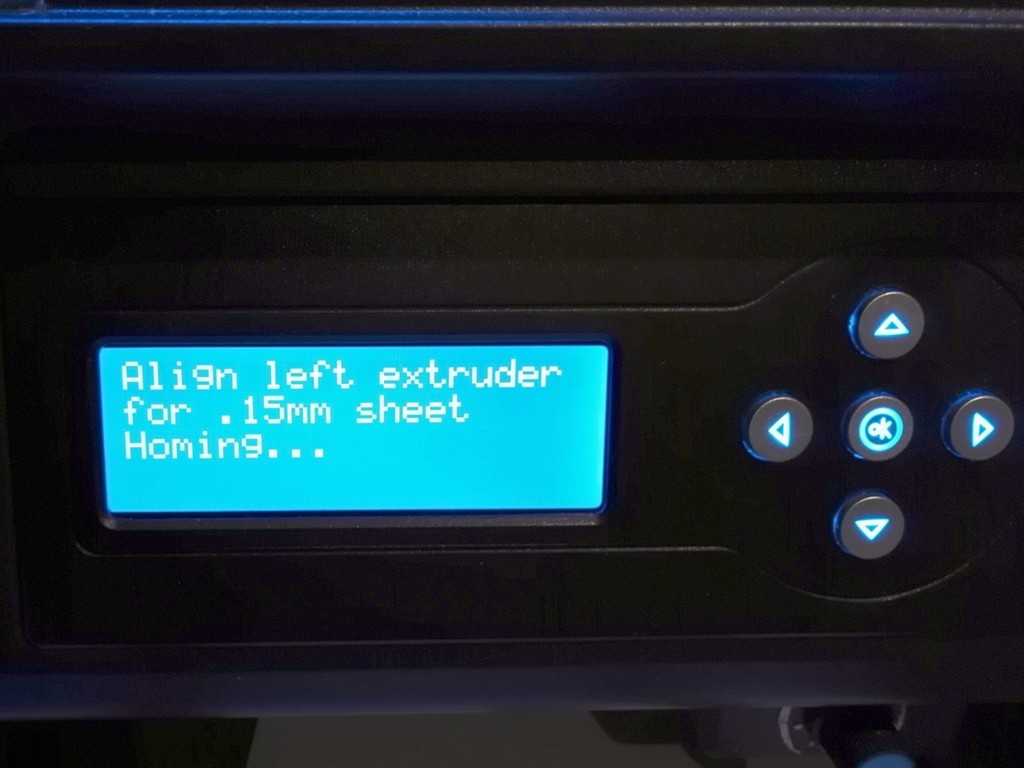
This is a set of x3g files that are intended to offer both much more flexibility and reliability than the default plate levelling file that comes with the FFCP. The improvements are: 1. There are specific files for levelling only the right (R), left (L), or both (LR) nozzles. 2. There are specific files for different levelling sheet thicknesses. 3. The nozzles, or the center between them, are positioned (nearly) exactly above each adjustment screw. 4. The nozzles are not placed inside the recessed zone of each screw, but just outside of it. This avoids inaccurate levelling if your print bed is covered with a non-rigid material like tape or BuildTak. 5. There are also advanced files that keep the bed, and optionally the extruders, heated during levelling. These files are meant for the FlashForge Creator Pro, but will probably work for similar printers with a 230x155 mm build plate as well. If you have a QIDI Tech 1, you need custom files (https://www.thingiverse.com/thing:3032840) due to the different positions of the levelling screws. (I included a simple cube STL file because Thingiverse requires at least one 3D model per Thing.) Using Files are offered for three different levelling sheet thicknesses: 0.10, 0.15, and 0.20 mm. Ideally, you should use the files with the number that matches the thickness in micrometers of your levelling sheet, divided by 10. For instance if you use a sheet that is 0.2 mm thick, use the ‘20’ files. If you don't know how thick your sheet is, you really should consider buying an accurate calliper or a micrometer. You can make an educated guess however: typical plain paper is usually 0.1 mm thick, the plastic levelling sheet that came with my FFCP is 0.2 mm thick, and some magazine covers and flyers are 0.15 mm thick. It is not a hard requirement to set up your printer such that you get perfect results with the files that match your feeler sheet, but it does make it much easier if you would change sheets later on. Then you would only need to switch to the set of files that match the new sheet's thickness. The regular files are named like: “Level-{extruders}-{sheet_thickness}”. If you're going to print with the left extruder only, use the ‘L’ files. Same for ‘R’ for right, and ‘LR’ for dual extrusions. An example: “Level-R-20.x3g” is the file for printing with the right extruder, when using a levelling sheet that is 0.2 mm (or 200 µm) thick. The less important files are provided in separate zip files, those are only for advanced use (see below). The procedure for using these files is as follows: 1. Choose the correct levelling file(s) and put it (them) on your SD card. 2. Each time you're going to print with a different extruder, or a different bed temperature than previously, do the following. 3. Preheat the bed (approximately) to the temperature you will be using during the print. You do not need to preheat the extruders, in fact I advise against it unless you know what you're doing. 4. ‘Print’ the levelling file and follow the instructions on the LCD. The nozzle will be positioned above each adjustment knob. ‘Tighten’ the knob (turn clockwise when viewing from underside) until you can slide your levelling sheet under the nozzle, then ‘loosen’ the knob until you feel a good deal of friction but can still easily move the sheet. Depending on the bed surface and particular filament, you may need to aim for slightly more or slightly less friction but you should never turn the knobs to a point where the sheet can no longer get under the nozzle. Verifying To verify that everything works correctly, do a test print with only one layer of known thickness. Measure how thick this printed layer is, using an accurate calliper or micrometer (again, if you don't have one, you really should). It should correspond roughly to the first layer thickness as configured in your slicer program. If it is way off, check the next paragraph. By ensuring that your first layer is printed at the correct thickness, you can reliably tweak the following things to get optimal adhesion: 1. First layer extrusion width. I usually take 150% of the nozzle diameter, i.e. 0.6 mm for a .4 nozzle. 2. First layer thickness. I never go below 0.25 mm for a 0.4 mm nozzle. You shouldn't make it higher than 2/3 of the extrusion width either. 3. First layer speed. I usually stay within the range of 20 to 30 mm/s. If your first layer is consistently too thick or thin… … then check the “Home offsets” setting in the printer's LCD menu and adjust the value for Z until your first layer has the expected thickness when following the above levelling procedure. If the printed layer is too thick, reduce the offset value and vice versa. For instance, after upgrading my FFCP's firmware, all my prints suddenly had way too tall first layers with horribly bad adhesion as a result. I measured the thickness of single-layer test prints, and they were consistently too thick by 0.15 mm. Somehow, the new firmware had changed the Z homing offset. By changing it to -0.15 mm in the menu, things were back to normal.
With this file you will be able to print Extended bed levelling code for FlashForge Creator Pro with your 3D printer. Click on the button and save the file on your computer to work, edit or customize your design. You can also find more 3D designs for printers on Extended bed levelling code for FlashForge Creator Pro.
