Exhaust Manifold
grabcad
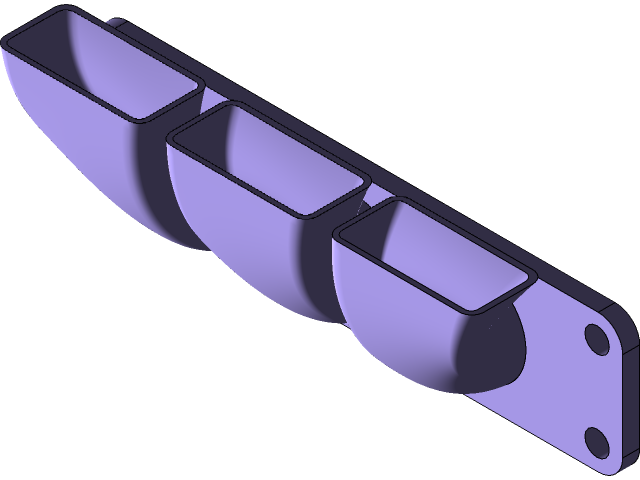
Designing an exhaust manifold in SolidWorks 2016 involves several key considerations to ensure optimal performance and efficiency. The process begins by creating a new part in SW2016, selecting the appropriate template, and specifying the material properties for the manifold. Next, engineers define the geometry of the exhaust manifold, taking into account factors such as flow rate, temperature, and pressure drops across the system. This involves modeling the manifold's shape, including the inlet and outlet ports, as well as any features that may affect gas flow, like bends or twists. To simulate the behavior of the exhaust gases, engineers use SW2016's built-in analysis tools to perform thermal and fluid dynamics simulations. These simulations help identify potential issues with the design, such as hot spots or areas where gas velocity is excessive. Once the initial design is complete, engineers refine the manifold by adjusting its geometry based on the simulation results. This may involve modifying the shape of the ports, changing the material properties, or adding features to improve flow characteristics. As the design reaches its final stages, engineers create a detailed drawing and documentation package in SW2016, including specifications for the manifold's materials, dimensions, and manufacturing processes. This ensures that the finished product meets all relevant safety and performance standards. Throughout the design process, collaboration with other stakeholders is crucial to ensure that the exhaust manifold meets the needs of the entire system. By working together and leveraging the capabilities of SW2016, engineers can create a high-performance exhaust manifold that optimizes engine efficiency and reduces emissions.
With this file you will be able to print Exhaust Manifold with your 3D printer. Click on the button and save the file on your computer to work, edit or customize your design. You can also find more 3D designs for printers on Exhaust Manifold.