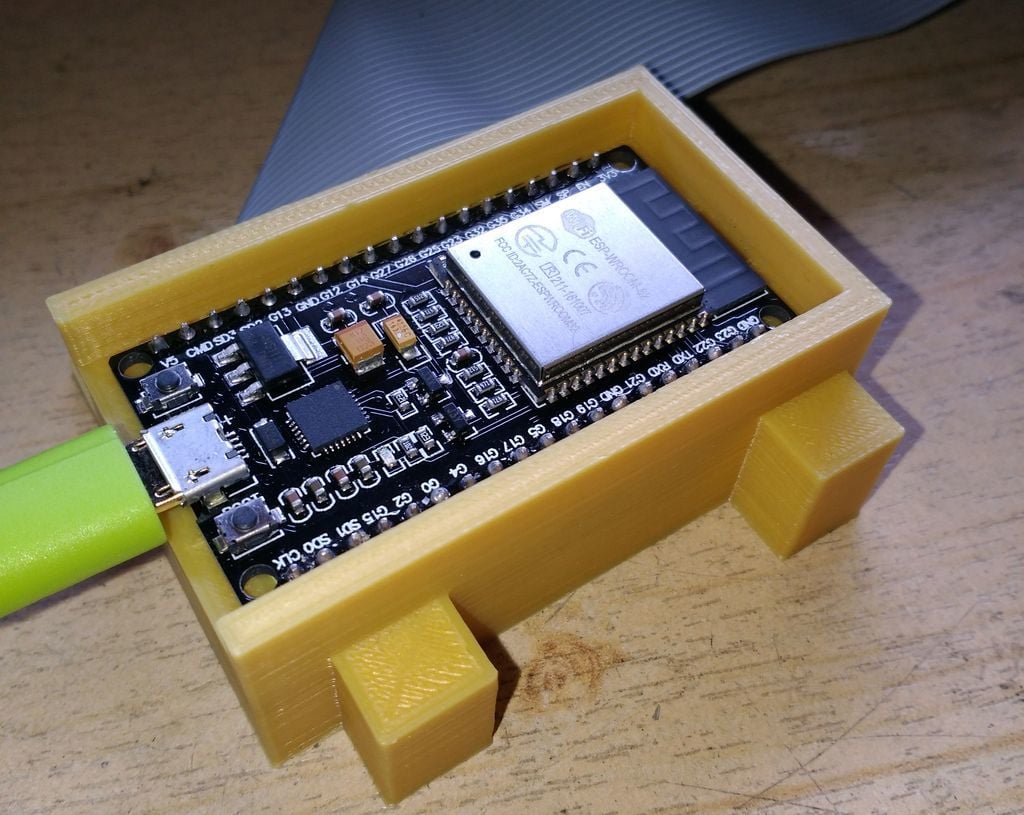
ESP32 devboard housing
thingiverse
I required a housing for the ESP-Wroom32 development board. Digging through the box of vintage electronics, I uncovered a 40-pin IDE cable that I repurposed as a socket for the board, which has 38 pins. If you aim to replicate this setup, be aware that newer cables often feature 80 lines or keypins. The provided STL file does not include the bricks I added to accommodate the floppy drive; instead, a FreeCAD file is included where you can customize your housing by adjusting several parameters in a spreadsheet. Don't forget to add space for material shrinkage. Notably, this design lacks a roof, which I plan to address using foil to minimize dampening of radio signals. Assembly involves positioning the wave connectors between the two drive connectors first. Next, feed the mainboard connector through the side hole from outside inwards, leaving other connectors inside. A hook is necessary to elevate the connectors again. This setup suits me well as-is, although it has ample room for improvement. Feel free to enhance it according to your needs.
With this file you will be able to print ESP32 devboard housing with your 3D printer. Click on the button and save the file on your computer to work, edit or customize your design. You can also find more 3D designs for printers on ESP32 devboard housing.
